These are the instructions for v1.2, if you have an older mintyboost you may want to check out the specific instructions for versions v1.1 (green PCB with v1.1 marking on the back and on the kit packaging) , version 1.0 is basically the same as v1.1 so just follow those instructions
The first step is to solder the kit together. If you've never soldered before, check the Preparation page for tutorials and more.
Some web browsers (basically, IE) do not like my website so much and load the photonotes slowly. So, if you are wondering where the rest of the instructions are, either wait a while and IE will eventually display it (below here). Or download Firefox/Safari which does not have this problem!
|
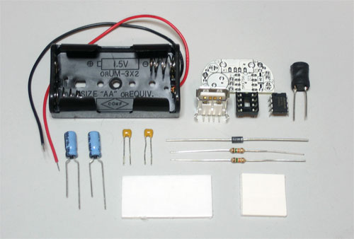
Check the kit to verify you have all the parts necessary |
 |
Get your space set up with a good light, a vice or "third-hand" tool, diagonal cutters, and a soldering iron/solder |
|
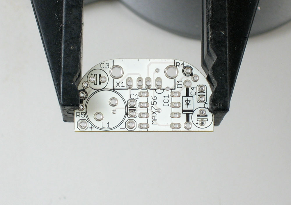
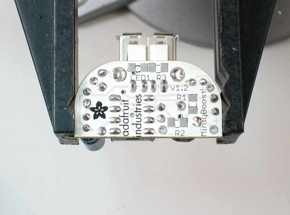
Put the circuit board in the vice, ready for soldering! |
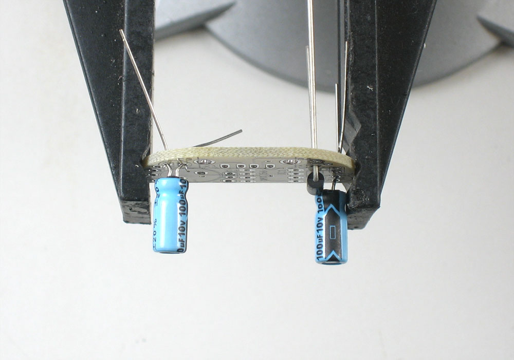 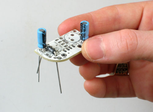 |
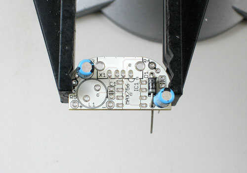
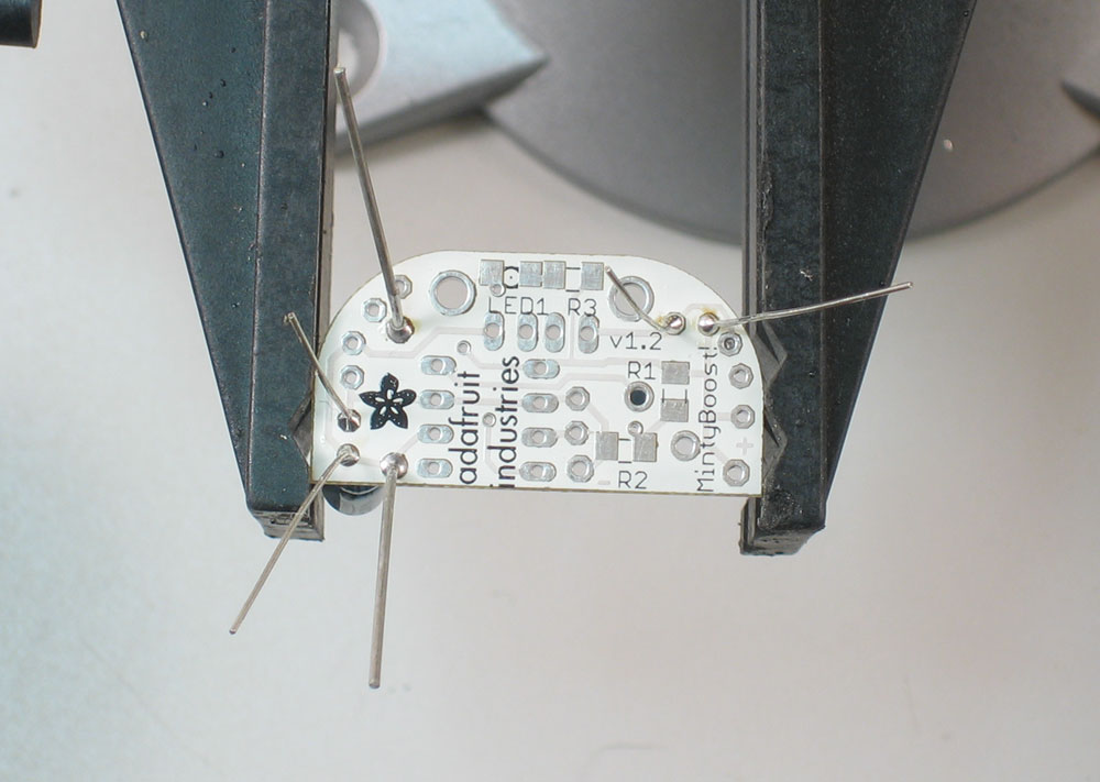
Place the two electrolytic capacitors C2 and C3 and the diode D1 in. Make sure you line up the white stripe on the diode with the white stripe in the picture on the circuit board. There are also white or black stripes with a minus sign on it on the capacitors, make sure they line up like in the picture to the left. If you're confused about the stripe, the side opposite to the stripe has a longer lead. When you put the parts in, bend the wire leads out a little so the parts stay up against the board when you turn it upside down to solder. |
|
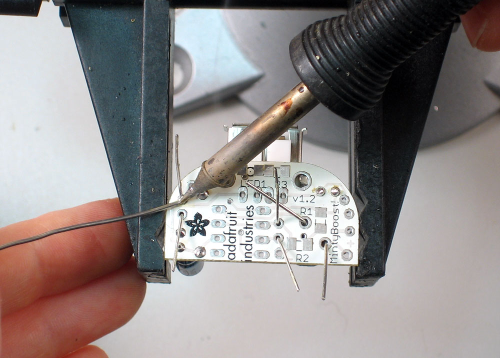
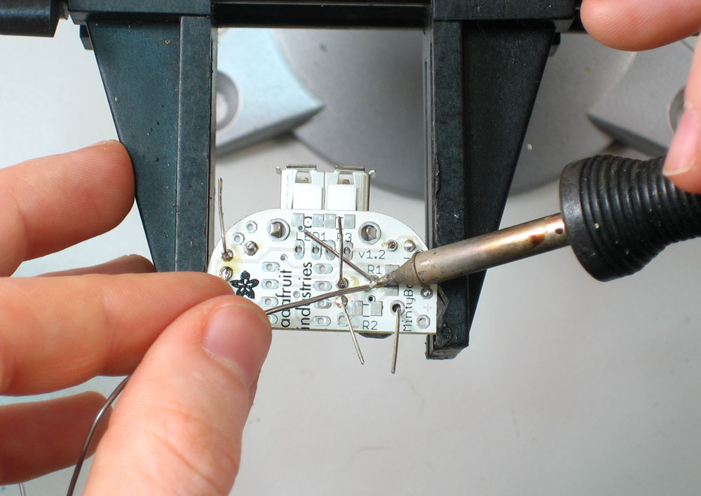
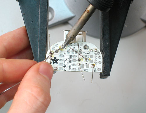
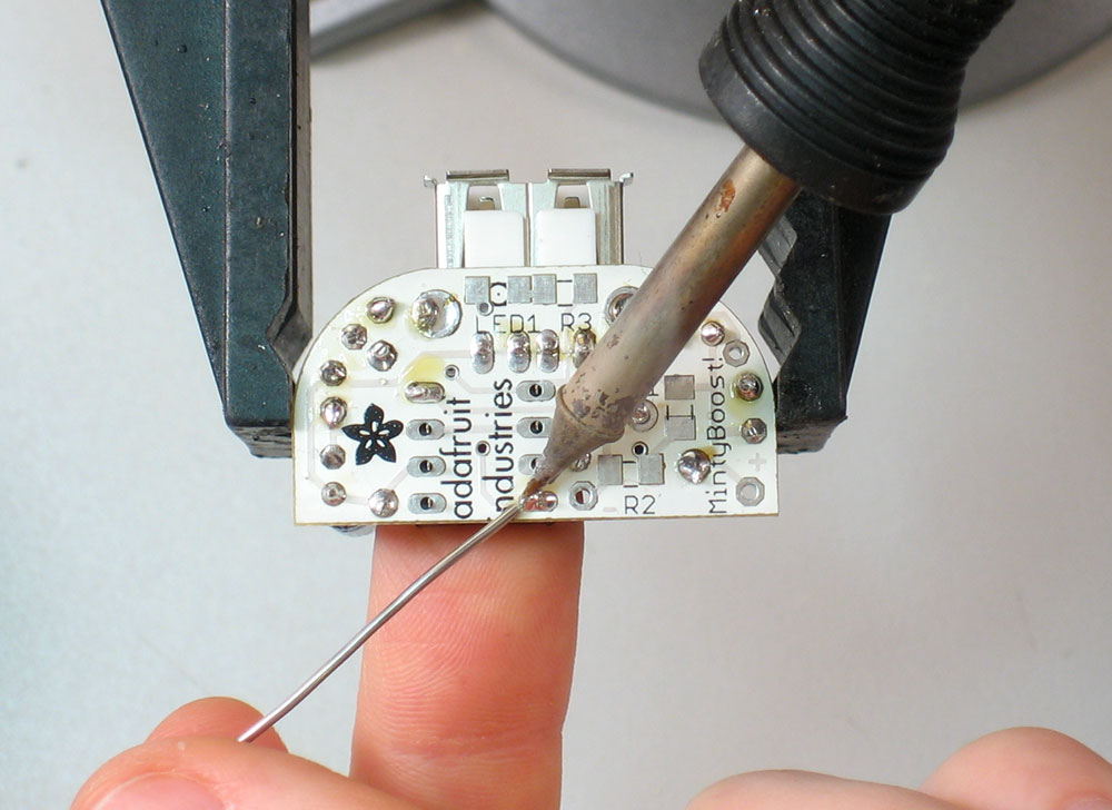
OK, now its time to solder. Make sure the iron is 650deg. Touch the tip at a 45deg angle so that its heating both the hole/ring and the wire lead, then touch/poke the solder in with your other hand. |
 |
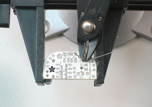
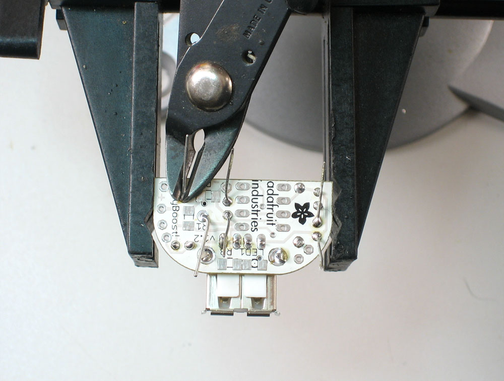
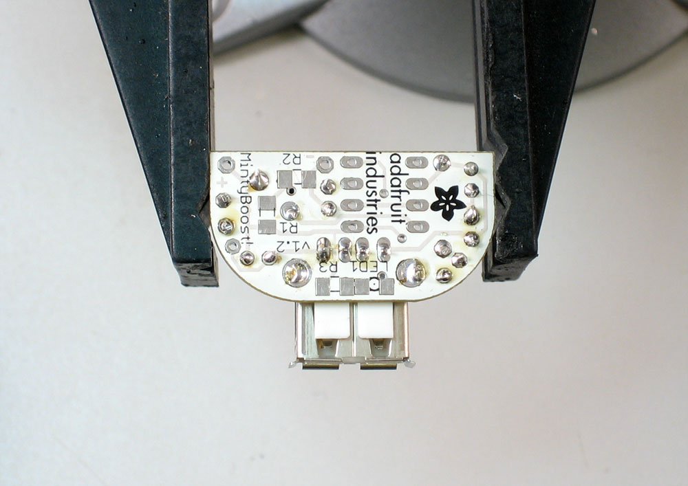
Clip the leads with the diagonal cutters. Be careful that the leads don't fly at your face. Cut the wires right above where the solder joint tapers off. Make sure the leads are not too long. Note in the picture how there are no pointy wire ends: these can end up poking through the foam and shorting the circuit against the metal tin, destroying all your hard work! |


|
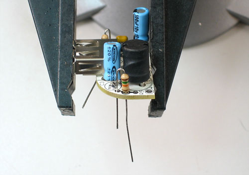
Place the two yellow ceramic capacitors C1 and C4, the power inductor L1 and the USB jack. The capacitors and inductor don't have a polarity, like the other capacitors and diode, so don't worry about putting them inbackwards.
Solder these parts in too. When soldering in the USB jack, make sure to put plenty of solder in the two large side holes: they are the mechanical connection for the jack. If you don't make a good solder joint (filling in the hole completely with solder) then the jack will eventually break! So do a good job. |
|
Clip the excess wires here too. Don't clip the USB jack leads: they're just the right size. |
|
Next, place R4 and R5, the 15K resistors. (For iPhone use, substitute the 100K resistors instead!) R4 is pretty straight-forward. R5, however, can be placed in two different ways. Both configurations are shown here, the top image shows "pullup" the bottom one shows "puldown" I suggest using the pullup configuration, and if it doesn't work, cutting the resistor lead and resoldering it as a pulldown. |
 |
Once you've chosen the configuration for R5 (these pictures assume it's a soldered in the pullup configuration) solder and clip the resistors |
|
Place the 8 pin socket so that the notch is next to the jack, just like the silkscreened image on the PCB. When soldering, you may have to hold the socket with a spare finger to keep it in place. Tack solder it in place. Then solder all of the pins. |

|
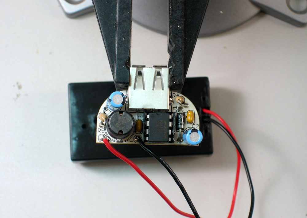
Put in the wires for the battery pack, make sure you don't mix them up! The red wire goes in the corner. |
|
|
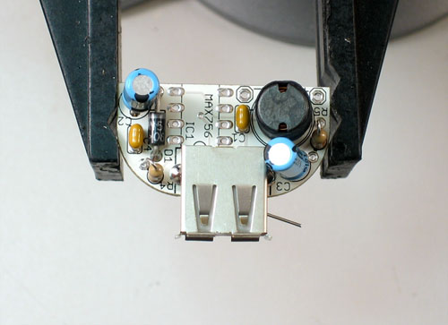
Nearly done! Insert the MAX756 boost chip so that the little notch in the chip matches the notch in the socket. Make sure its well seated: press firmly, making sure all the pins are sliding into the socket straight. You're done! |


Mintyboost® is a registered trademark of Adafruit Industries