This is an old revision of the document!
Table of Contents
What is a power supply?
A power supply is a device that supplies power to another device, at a specific voltage level, voltage type and current level. For example, when we talk about a 9VDC @ 500mA power supply can provide as much as 500mA of current and the voltage will be at least 9V DC up to that maximum current level. While it sounds simple, power supplies have a lot of little hang-ups that can be very tricky for the uninitiated. For example, unregulated supplies say they can provide 9V but really may be outputting 15V! The very common 7805 regulator datasheet claims it can regulate up to 1000 mA of current, but when you put a 15V supply on one side, it overheats and shuts down! This tutorial will try to help explain all about power supplies.
Why a power supply?
When you start out with electronics, you'll hear a lot about power supplies - they're in every electronics project and they are the backbone of everything! A good power supply will make your project hum along nicely. A bad power supply will make life frustrating: stuff will work sometimes but not others, inconsistent results, motors not working, sensor data always off. Understanding power supplies (boring though they may be) is key to making your project work!
A lot of people don't pay much attention to power supplies until problems show up. We think you should always think about your power supply from day one - How are you going to power it? How long will the batteries last? Will it overheat? Can it get damaged by accidentally plugging in the wrong thing?
Power supplies are all around you!
Unless you live in a shack in the woods, you probably have a dozen power supplies in your home or office.
Here is the power supply that is used in many apple products:
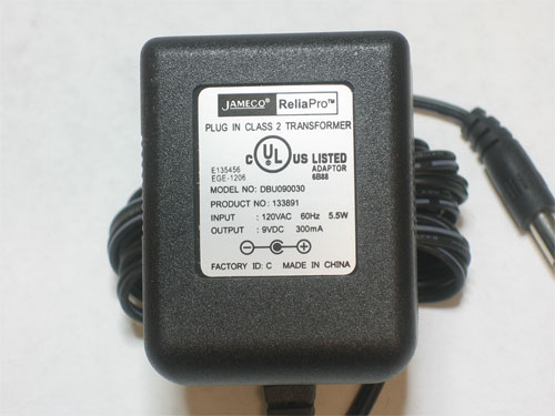
Here is a classic 'wall wart' that comes with many consumer electronics:
This is a massive power supply that's in a PC, usually you dont see this unless you open up the PC and look inside for the big metal box
All these power supplies have one thing in common - they take high voltage 120V or 220V AC power and regulate or convert it down to say 12V or 5V DC. This is important because the electronics inside of a computer, or cell phone, or video game console dont run at 120V and they don't run on AC power!
So, to generalize, here is what the power supplies for electronics do:
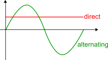
- They convert AC (alternating current) power to DC (direct current)
- They regulate the high voltage (120-220V) down to around 5V (the common voltages range from 3.3V to 15V)
- They may have fuses or other overcurrent/overheat protection
Hey, so if electronics can't run on AC, why doesn't wall power come in DC?
You may be wondering - "I have 20 wall adapters, this seems silly! Why not just have DC power come out of the wall at 5V?" Essentially, because modern electronics are very recent. for many many decades wall power was used to power light bulbs, big motors (like fridges, vacuum cleaners, washing machines, air conditioners), and heaters. All of these use AC power more efficiently than DC power. Also, different electronics need different voltages. So far its worked out better to have a custom power supply for each device although it is a little irritating sometimes!
AC/DC
So the power coming out of your wall is high voltage AC but microcontrollers and servos and sensors all want low voltage DC. How shall we make it work? Converting between AC power and DC power requires different techniques depending on what the input and output is. We'll refer to this table
| Power type in | Power type out | Technique | Pros | Cons | Commonly seen… |
|---|---|---|---|---|---|
| High Voltage AC (eg. 120V-220VAC) | Low voltage AC (eg. 12VAC) | Transformer | Really cheap, electrically isolated | Really big & heavy! | Small motors, in cheaper power supplies before the regulator |
| Low Voltage AC (eg. 20VAC) | High voltage AC (eg ~120VAC) | Transformer | Same as above, but the transformer is flipped around | Really big & heavy! | Some kinds of inverters, EL wire or flash bulb drivers |
| " | " | AC 'voltage doubler' | Uses some diodes and capacitors, very cheap | Not isolated! Low power output | |
| High Voltage AC (eg. 120V-220VAC) | High voltage DC (eg. 170VDC) | Half or full wave rectifier | Very inexpensive (just a diode or two) | Not isolated | We've seen these in tube amps |
| Low Voltage AC (eg. 20VAC) | Low voltage DC (eg 5VDC) | Half or full wave rectifier | Very inexpensive (just a diode or two) | Not isolated | Practically all consumer electronics that have transformer-based supplies |
| High Voltage AC (eg. 120V-220VAC) | Low voltage DC (eg 5VDC) | Transformer & rectifier Combination of High→Low AC & Low AC→Low DC | Fairly inexpensive | Kinda heavy, output is not precise, efficiency is so-so | Every chunky wall-wart contains this |
| High Voltage AC (eg. 120V-220VAC) | Low voltage DC (eg 5VDC) | Switching supply | Light-weight, output is often precise | Expensive! | Every slimmer wall-wart contains this |
Basically, to convert from AC to AC we tend to use a transformer. To convert from AC to DC we use a transformer + diodes (rectifier) or a switching supply. The former is inexpensive (but not very precise) and the later is expensive (but precise). Guess which one you're more likely to find in a cheaply-made device? :)
The good old days!
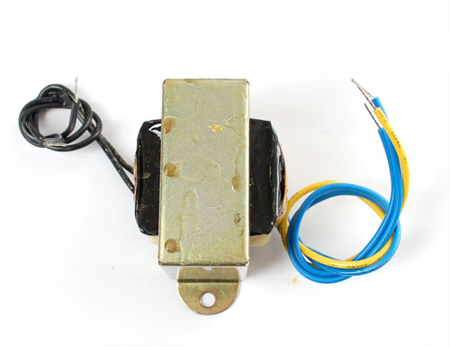
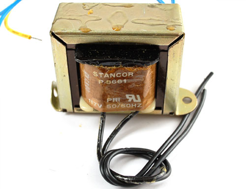
Back a couple decades ago, the popular way to build a power supply was to get a big chunky 120VAC/12VAC transformer. We aren't going to get into the heavy detail of the electromagnetic theory behind transformers except to say that they are made of two coils of wire around a chunk of iron. If the number of coils are the same on both sides then the AC voltage is the same on both sides. If one side has twice the coils, it has twice the voltage. They can be used 'backwards' or 'forwards'! For more detailed information, check out the wikipedia page
To use it, one half would get wired up to the wall (the 'primary' 'high side')
and the other half would output 12V AC (the 'secondary' 'low side'). The transformer functioned in two ways: one it took the dangerous high voltage and transformed it to a much safer low voltage, second it isolated the two sides. That made it even safer because there was no way for the hot line to show up in your electronics and possibly electrocute you.
We'll use a schematic symbol to indicate a transformer, its two coils inside which are drawn out, the schematic symbol will have the same number of coils on either side so use common sense and any schematic indicators to help you out in figuring which is primary and which is secondary!
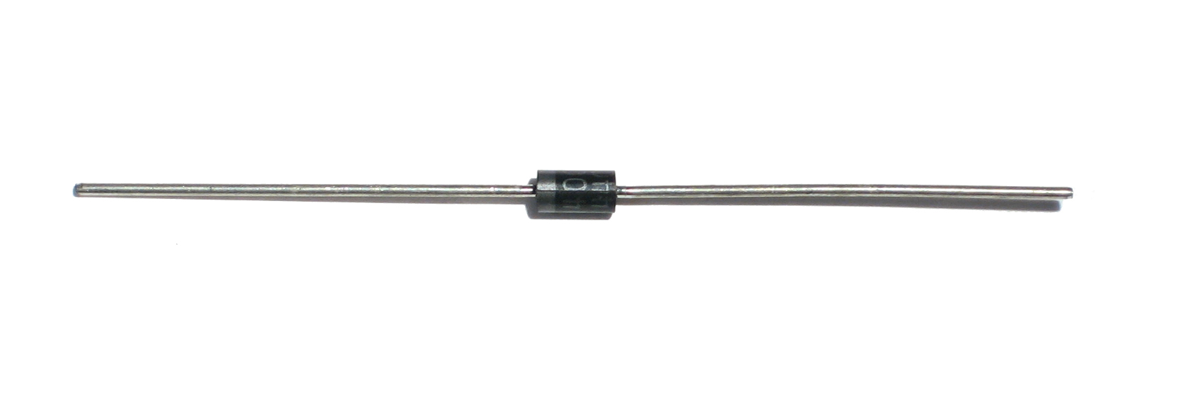
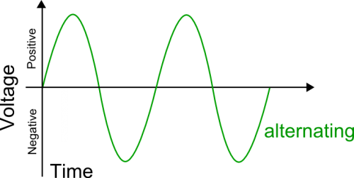
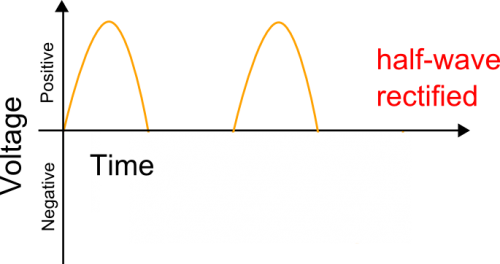
Now that the voltage was at a non-electrocutey level of around 12VAC it could be converted into DC. The easiest and cheapest way to convert AC to DC is to use a single diode. A diode is a simple electronic 'valve' - it only lets current flow one way. Since AC voltage cycles from positive to negative and we only want positive, we can connect it up so that the circuit only receives the positive half of the AC cycle.
The output is then chopped in half so that the voltage only goes positive
This will convert
into


