This is an old revision of the document!
Table of Contents
Introduction
Last week we showed how to use an Arduino + protoshield + ZIF socket to make a programmer that can burn a lot of Arduino bootloaders. In our blog comments a user commented that he had written a stand-alone program for the Arduino called Optiloader that is similar and might be worth checking out.
What Optiloader does is kinda of neat. Instead of having a computer that talks thru the Arduino to a chip for programming, instead the Arduino itself programs the chip. This means you can program chips without having a computer involved. The good news about this technique is that it is incredibly fast, you can program chips 10x faster than with a computer and without having to type anything in. The only downside is that its very specialized, once you set it up the programmer can only do one chip (in general) with one HEX file. If you want to update it, it can be a little effort to reconfigure.
However, if you are burning a lot of chips, this can be a real blessing. We can program and burn an Arduino bootloader chip in about 5 seconds. Normally with a computer you're talking 40 seconds or so. Another nice thing is that you can make it very clear when a failure has occured. Instead of reading text on a computer screen - a piezo will beep once on success. We've found that audio feedback is way more likely to be noticed than visual feedback.
We adapted Optiloader to be more flexible - so it can program any AVR with any HEX file. While you dont need to use an Arduino for this, we have a lot of Arduino's kicking around here so they make a handy base.
This code can be adapted for programming any AVR that can be ISP programmed (this is like 99% of AVRs) but in this example the wiring will be for the Atmega8/48/88/168/328 series and the code will be the Adaboot bootloader. If you have other chips you are programming, check the datasheet for how to wire VCC, Gnd, MISO, MOSI, SCK, RST and XTAL1 (if you need external clocking)
Assembling the standalone programming shield
To complete this tutorial you will need…
- Blank ATmega328P (that you will program)
First up, place the ZIF socket on the proto shield like so:
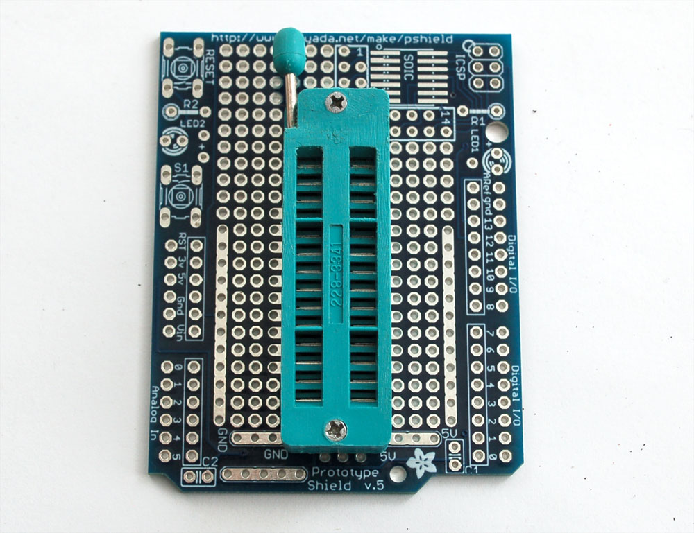
Solder all 28 pins for a solid connection!
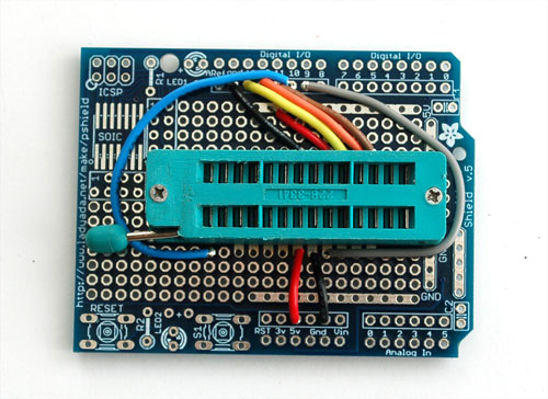
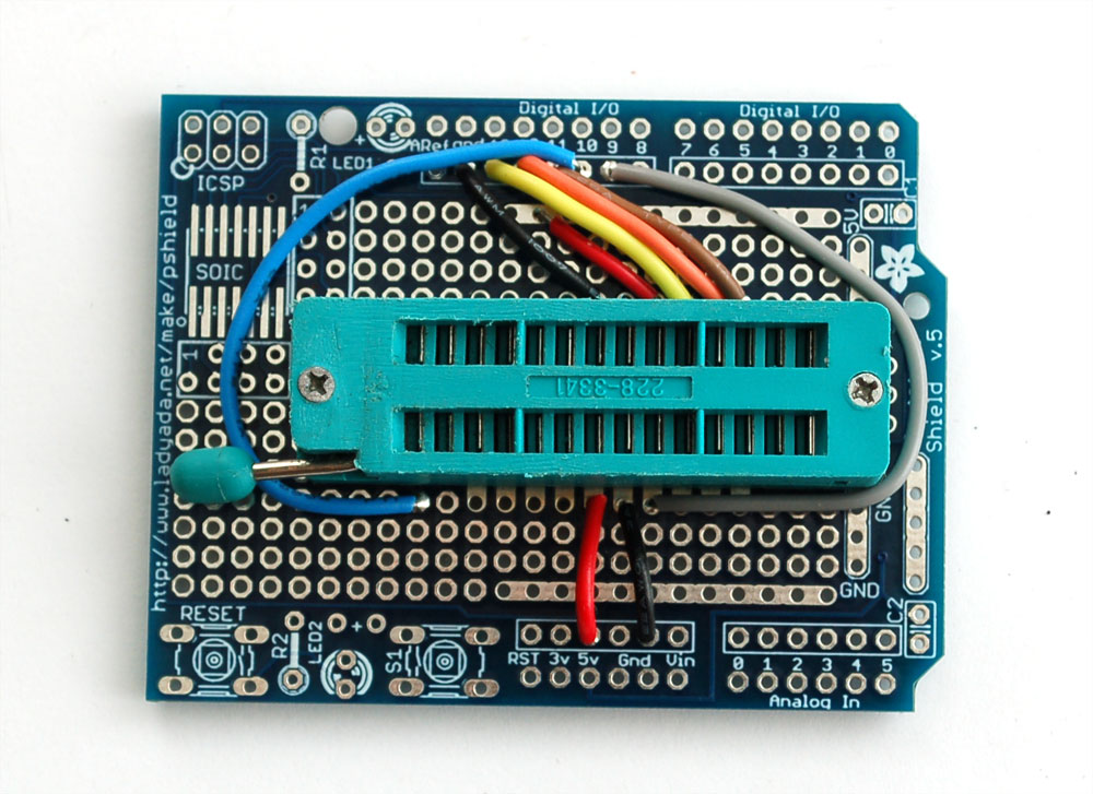
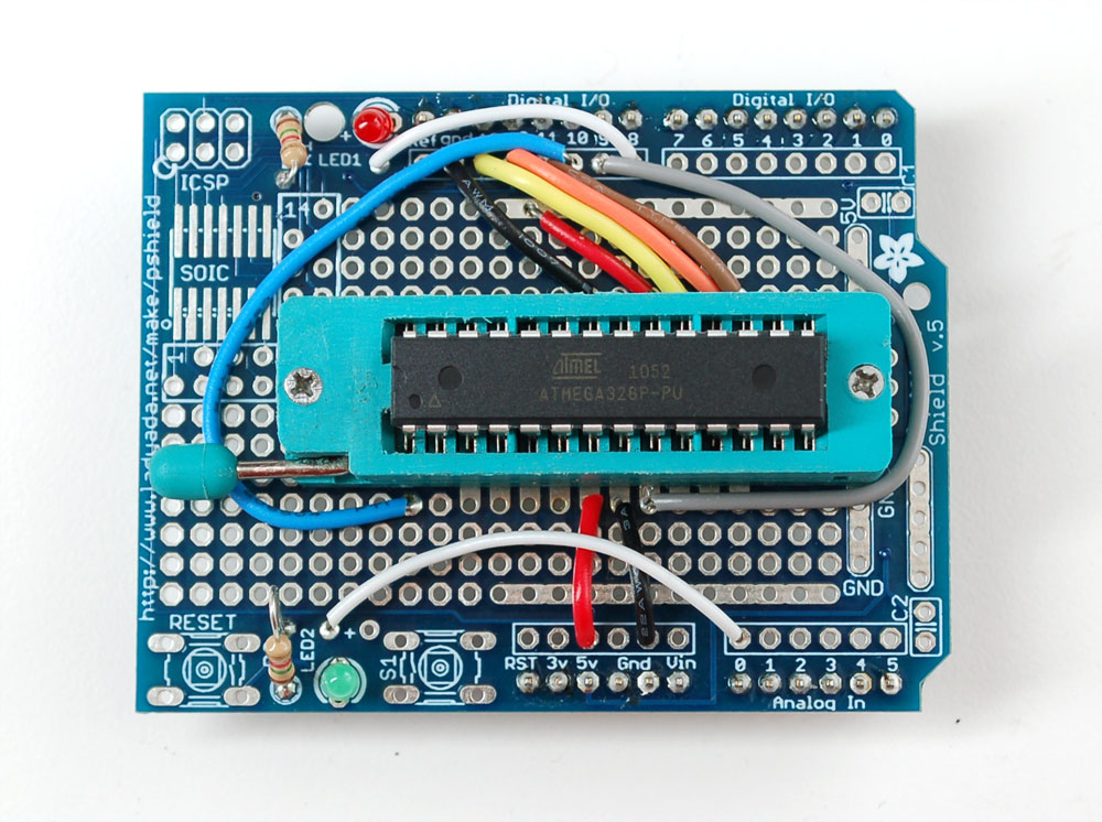
Solder the following wires to the ZIF socket
- Pin 1 to digital 10 - Blue (this wire connects underneath to the ZIF socket so make sure to 'jumper it so it solders directly to the ZIF pin, see the photos below)
- Pin 7 to 5V - Red
- Pin 8 to Ground - Black
- Pin 9 to digital 9 - Gray
- Pin 17 to digital 11 - Brown
- Pin 18 to digital 12 - Orange
- Pin 19 to digital 13 - Yellow
- Pin 20 to +5V - Red
- Pin 22 to Ground - Black
Follow the protoshield tutorial to solder in the Red LED into LED1 position, Green LED into LED2 position. Also solder in the two 1.0K resistors next to the LEDs. We'll use the LEDs as indicators. Then solder a wire from the LED2 breakout (white) to analog 0 and a wire from LED1 breakout (white) to digital 8
Next add S1switch which you will press to start the programming process. You can just solder a wire (yellow) from the breakout near S1 to Analog 1
We also soldered in a Piezo beeper, to give us feedback. One side is soldered into Analog 3 the other side is soldered to the ground rail right next to the analog breakouts.
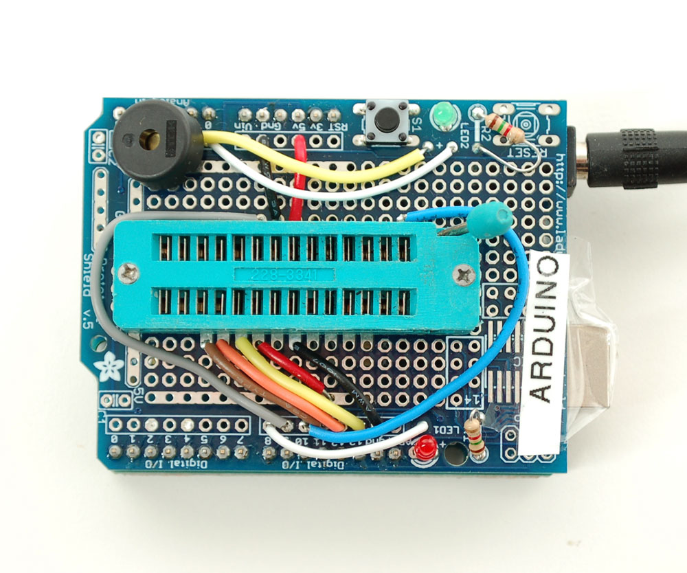
Finally, you'll need to solder on the header to allow the shield to be placed on, break the 0.1" male header and place it into the Arduino sockets. Then place the shield above on top to solder it in place
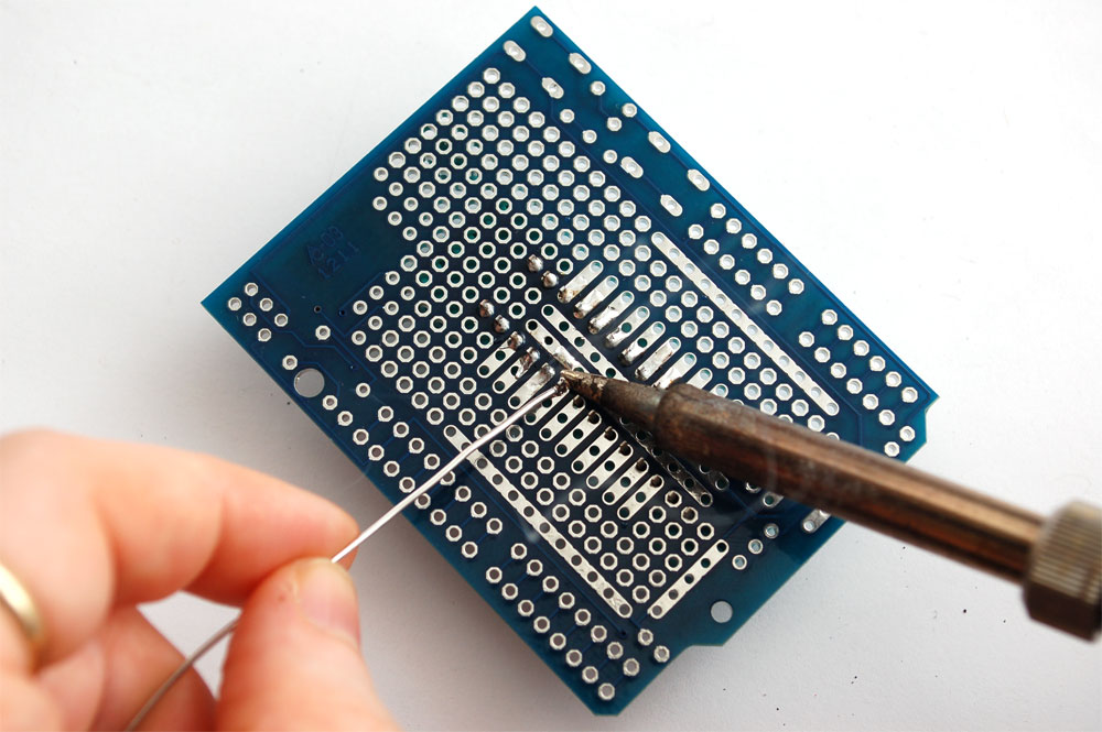
If you need to see what the bottom looks like, it will be something like this. Except ours has a ton of rosin on it because we ended up moving the socket for this prototype, so that brown rosin stuff probably wont be on yours!
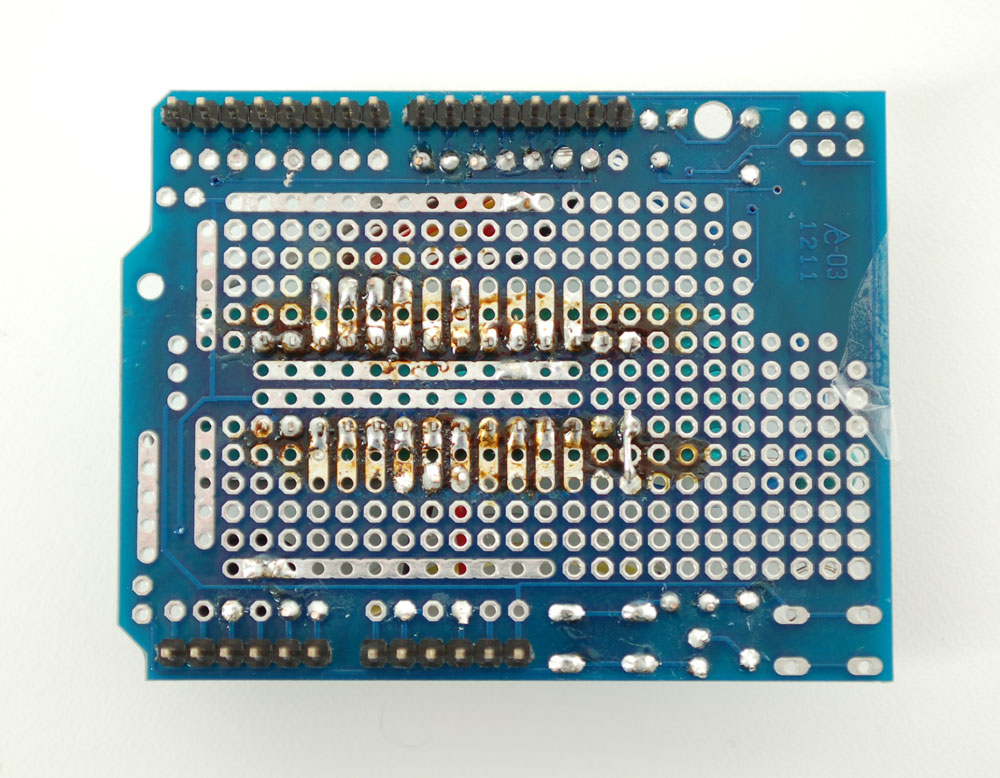
Thats it!
Next, download the codebase from github. Make a sketch floader called adaLoader in your Arduino sketch collection and copy the pde and helper files in. Restart the IDE and open up that sketch, compile it and upload it to your Arudino.
Now you can use it, very easy…just insert the chip, lock it down and press the button. While programming, the green LED is lit. When done, the piezo will beep once. If the red LED is lit, a problem occured
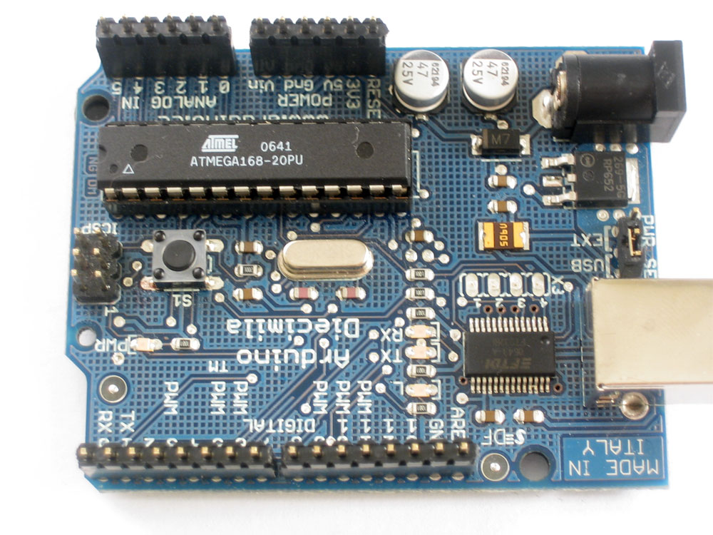
Once you have programmed the chip with our default code you can use it in an existing Arduino board, compatible, or breadboard style. You will need a 16 MHz crystal on the clock pins, so don't forget it!
The standalone sketch will only program ATmega328P chips and it will program them with our "adaBoot" Bootloader not Optiboot! Select Duemilanove with 328 when uploading to Arduinos that use the bootloaded chip, even if you are using it in an UNO branded Arduino!
Changing the code
Unlike the specialized Optiloader, this program can be adapted to any AVR and any size HEX file as long as you can fit the HEX into the flash of the microcontroller. Since HEX files are ascii, they basically 2x the size of the code itself. So if you have a 500 byte program, the HEX will be 1K. The sketch itself takes about 10KB so you have approximately 20KB left for the HEX which is good for about 10KB of flash to burn. This isn't tons but I suppose if you wanted to port the program to the Mega then you could fit up to 128KB of flash for massive chips.
You can paste your new HEX into images.cpp. You'll need also to set the bottom two bytes of the signature (third entry), and the fuses you want to set before you start programming, and the fuses you want to set after programming (in case the lock bits have changed). The fuse mask is used because not all fuse bits are used so if you write a zero to an unused bit (as avrdude prefers to do) it may be read back as a 1 which can cause verification errors. Next is the size of the chip flash in bytes and the size of a flash page for the chip (you may need to research the datasheet for this number). The first two arguments (name of flash and name of chip) are for your records, they arent really used by the program itself.
After you've adjusted those, go back to the main pde sketch and update
byte pageBuffer[128]; /* One page of flash */
so that the size of the flash page buffer is larger if necessary
Please note that while this tutorial works and we're very confident that this project can be adapted to other chips making sure that you have all the above set correctly is not trivial and will take some trial and error as well as expertise in reading datasheets and the avrdude.conf file so we can't provide one-on-one technical support in helping you adapt the tutorial to your particular chip and code. Please endeavor to work it out on your own!
Of course, after you load a new firmware in, be sure to check that it did in fact burn it correctly using a known good programmer.
