This is an old revision of the document!
Table of Contents
Overview
The Adafruit_GFX library for Arduino provides a common syntax and set of graphics functions for all of our LCD and OLED displays. This allows Arduino sketches to easily be adapted between display types with minimal fuss…and any new features, performance improvements and bug fixes will immediately apply across our complete offering of color displays.
The Adafruit_GFX library works together with a second library provided for each specific display type — for example, the ST7735 1.8" color LCD requires installing both the Adafruit_GFX and Adafruit_ST7735 libraries. For information how to use and install libraries, see our tutorial!
The libraries are written in C++ for Arduino but could easily be ported to any microcontroller by rewriting the low-level pin access functions.
Coordinate System and Units
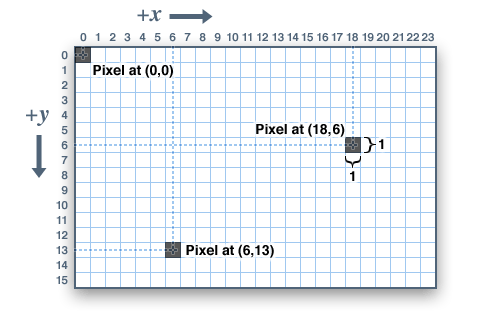
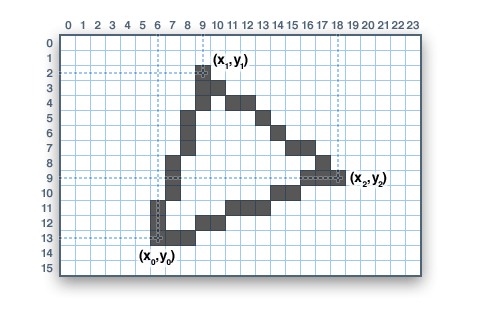
Pixels — picture elements, the blocks comprising a digital image — are addressed by their horizontal (X) and vertical (Y) coordinates. The coordinate system places the origin (0,0) at the top left corner, with positive X increasing to the right and positive Y increasing downward. This is upside-down relative to the standard Cartesian coordinate system of mathematics, but is established practice in many computer graphics systems (a throwback to the days of raster-scan CRT graphics, which worked top-to-bottom). To use a tall “portrait” layout rather than wide “landscape” format, or if physical constraints dictate the orientation of a display in an enclosure, one of four rotation settings can also be applied, indicating which corner of the display represents the top left.
Also unlike the mathematical Cartesian coordinate system, points here have dimension — they are always one full integer pixel wide and tall.
Coordinates are always expressed in pixel units; there is no implicit scale to a real-world measure like millimeters or inches, and the size of a displayed graphic will be a function of that specific display’s dot pitch or pixel density. If seeking a specific real-world dimension, you’ll need to scale your coordinates to suit. Dot pitch can often be found in the device datasheet, or by measuring the screen width and dividing the number of pixels across by this measurement.
For color-capable displays, colors are represented as unsigned 16-bit values. Some displays may physically be capable of more or fewer bits than this, but the library operates with 16-bit values…these are easy for the Arduino to work with while also providing a consistent data type across all the different displays. The primary color components — red, green and blue — are all “packed” into a single 16-bit variable, with the most significant 5 bits conveying red, middle 6 bits conveying green, and least significant 5 bits conveying blue. That extra bit is assigned to green because our eyes are most sensitive to green light. Science!

For the most common primary and secondary colors, we have this handy cheat-sheet that you can include in your own code. Of course, you can pick any of 65,536 different colors, but this basic list may be easiest when starting out:
// Color definitions
#define BLACK    0x0000
#define BLUE     0x001F
#define RED      0xF800
#define GREEN    0x07E0
#define CYAN     0x07FF
#define MAGENTA  0xF81F
#define YELLOW   0xFFE0
#define WHITE    0xFFFF
For monochrome (single-color) displays, colors are always specified as simply 1 (set) or 0 (clear). The semantics of set/clear are specific to the type of display: with something like a luminous OLED display, a “set” pixel is lighted, whereas with a reflective LCD display, a “set” pixel is typically dark. There may be exceptions, but generally you can count on 0 (clear) representing the default background state for a freshly-initialized display, whatever that works out to be.
Graphics Primitives
Each device-specific display library will have its own constructors and initialization functions. These are documented in the individual tutorials for each display type, or oftentimes are evident in the specific library header file. The remainder of this tutorial covers the common graphics functions that work the same regardless of the display type.
The function descriptions below are merely prototypes — there’s an assumption that a display object is declared and initialized as needed by the device-specific library. Look at the example code with each library to see it in actual use. For example, where we show print(1234.56), your actual code would place the object name before this, e.g. it might read screen.print(1234.56) (if you have declared your display object with the name screen).
Drawing pixels (points)
First up is the most basic pixel pusher. You can call this with X, Y coordinates and a color and it will make a single dot:
void drawPixel(uint16_t x, uint16_t y, uint16_t color);
![]()
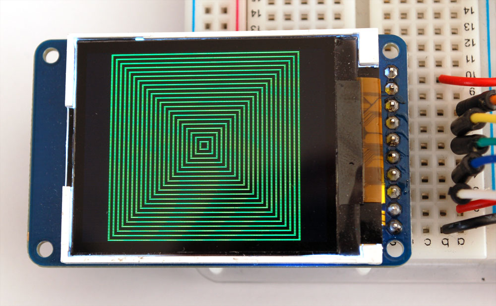
Drawing lines
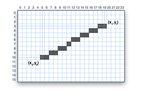
You can also draw lines, with a starting and end point and color:
void drawLine(uint16_t x0, uint16_t y0, uint16_t x1, uint16_t y1, uint16_t color);
For horizontal or vertical lines, there are optimized line-drawing functions that avoid the angular calculations:
void drawFastVLine(uint16_t x0, uint16_t y0, uint16_t length, uint16_t color);

void drawFastHLine(uin86_t x0, uin86_t y0, uint8_t length, uint16_t color);
Rectangles
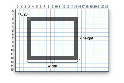
Next up, rectangles and squares can be drawn and filled using the following procedures. Each accepts an X, Y pair for the top-left corner of the rectangle, a width and height (in pixels), and a color. drawRect() renders just the frame (outline) of the rectangle — the interior is unaffected — while fillRect() fills the entire area with a given color:
void drawRect(uint16_t x0, uint16_t y0, uint16_t w, uint16_t h, uint16_t color);

void fillRect(uint16_t x0, uint16_t y0, uint16_t w, uint16_t h, uint16_t color);
To create a solid rectangle with a contrasting outline, use fillRect() first, then drawRect() over it.
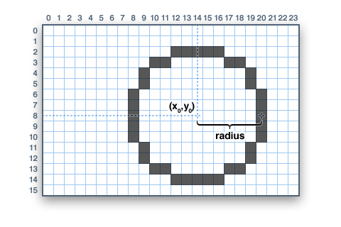
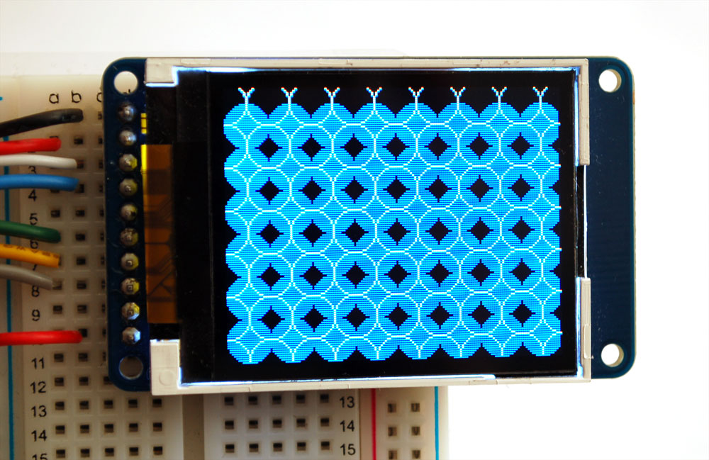
Circles
Likewise, for circles, you can draw and fill. Each function accepts an X, Y pair for the center point, a radius in pixels, and a color:
void drawCircle(uint16_t x0, uint16_t y0, uint16_t r, uint16_t color);

void fillCircle(uint16_t x0, uint16_t y0, uint16_t r, uint16_t color);
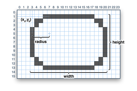
Rounded rectangles
For rectangles with rounded corners, both draw and fill functions are again available. Each begins with an X, Y, width and height (just like normal rectangles), then there’s a corner radius (in pixels) and finally the color value:
void drawRoundRect(uint16_t x0, uint16_t y0, uint16_t w, uint16_t h, uint16_t radius, uint16_t color);

void fillRoundRect(uint16_t x0, uint16_t y0, uint16_t w, uint16_t h, uint16_t radius, uint16_t color);
Here’s an added bonus trick: because the circle functions are always drawn relative to a center pixel, the resulting circle diameter will always be an odd number of pixels. If an even-sized circle is required (which would place the center point between pixels), this can be achieved using one of the rounded rectangle functions: pass an identical width and height that are even values, and a corner radius that’s exactly half this value.
Triangles
With triangles, once again there are the draw and fill functions. Each requires a full seven parameters: the X, Y coordinates for three corner points defining the triangle, followed by a color:
void drawTriangle(uint16_t x0, uint16_t y0, uint16_t x1, uint16_t y1, uint16_t x2, uint16_t y2, uint16_t color);
void fillTriangle(uint16_t x0, uint16_t y0, uint16_t x1, uint16_t y1, uint16_t x2, uint16_t y2, uint16_t color);
Characters and text
There are two basic string drawing procedures for adding text. The first is just for a single character. You can place this character at any location and with any color. There’s only one font (to save on space) and it’s meant to be 5x8 pixels, but an optional size parameter can be passed which scales the font by this factor (e.g. size=2 will render the text at 10x16 pixels per character). It’s a little blocky but having just a single font helps keep the program size down.
void drawChar(uint16_t x, uint16_t y, char c, uint16_t color, uint8_t size);

Text is very flexible but operates a bit differently. Instead of one procedure, the text size, color and position are set up in separate functions and then the print() function is used — this makes it easy and provides all of the same string and number formatting capabilities of the familiar Serial.print() function!
void setCursor(uint16_t x0, uint16_t y0);
void setTextColor(uint16_t color);
void setTextColor(uint16_t color, uint16_t backgroundcolor);
void setTextSize(uint8_t size);
Begin with setCursor(x, y), which will place the top left corner of the text wherever you please. Initially this is set to (0,0) (the top-left corner of the screen). Then set the text color with setTextColor(color) — by default this is white. Text is normally drawn “clear” — the open parts of each character show the original background contents, but if you want the text to block out what’s underneath, a background color can be specified as an optional second parameter to setTextColor(). Finally, setTextSize(size) will multiply the scale of the text by a given integer factor. Below you can see scales of 1 (the default), 2 and 3. It appears blocky at larger sizes because we only ship the library with a single simple font, to save space.
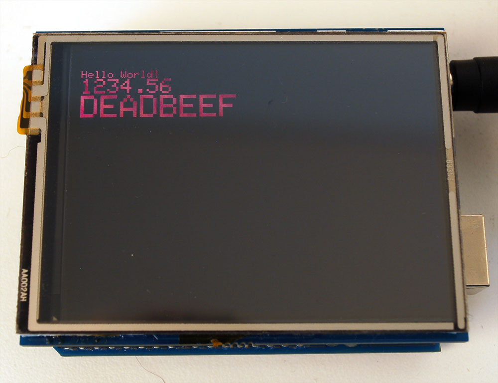
After setting everything up, you can use print() or println() — just like you do with Serial printing! For example, to print a string, use print("Hello world") - that’s the first line of the image above. You can also use print() for numbers and variables — the second line above is the output of print(1234.56) and the third line is print(0xDEADBEEF, HEX).
Bitmaps
You can draw small monochrome (single color) bitmaps, good for sprites and other mini-animations or icons:
void drawbitmap(uint8_t x, uint8_t y, const uint8_t *bitmap, uint8_t w, uint8_t h, uint8_t color);
(Extended description is forthcoming — this is a somewhat advanced function that relies on PROGMEM, so beginners are best advised to steer clear of this for now.)
Clearing or filling the screen
The fillScreen() function will set the entire display to a given color, erasing any existing content:
void fillScreen(uint16_t color);
Rotating the display
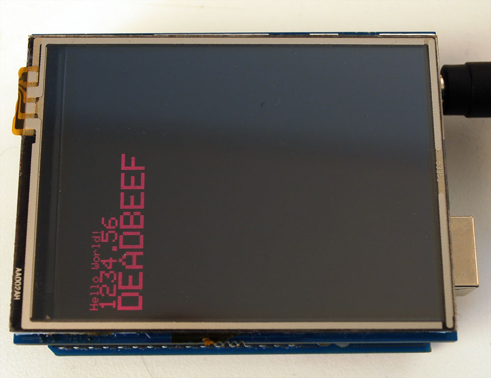
You can also rotate your drawing. Note that this will not rotate what you already drew, but it will change the coordinate system for any new drawing. This can be really handy if you had to turn your board or display sideways or upside down to fit in a particular enclosure. In most cases this only needs to be done once, inside setup().
void rotate(uint8_t rotation);
The rotation parameter can be 0, 1, 2 or 3. For displays that are part of an Arduino shield, rotation value 0 sets the display to a portrait (tall) mode, with the USB jack at the top right. Rotation value 2 is also a portrait mode, with the USB jack at the bottom left. Rotation 1 is landscape (wide) mode, with the USB jack at the bottom right, while rotation 3 is also landscape, but with the USB jack at the top left.
When rotating, the origin point (0,0) changes — the idea is that it should be arranged at the top-left of the display for the other graphics functions to make consistent sense (and match all the function descriptions above).
If you need to reference the size of the screen (which will change between portrait and landscape modes), use width() and height().
uint16_t width();
uint16_t height();
Each returns the dimension (in pixels) of the corresponding axis, adjusted for the display’s current rotation setting.
