Table of Contents
Programmable LED belt!
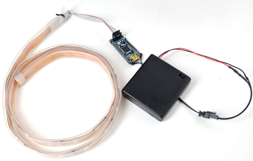
By popular demand, we now have a project tutorial for how to make your own programmable, ultra-blinky LED belt. Perfect for parties, raves, parades, weddings, funerals, and bar mitzvahs. Wear it with pride, wear it with blinky! Follow this tutorial to build your own heirloom LED belt, and hand it down to your grandkids.
We designed this project to demonstrate how to use the digital LED strip, how to use our Atmega32u4 breakout board with the Arduino IDE and how to make a portable battery powered project that runs off of AAs. This project is not too difficult, and can be finished in a day. Some soldering experience is good since 'free wire' soldering is a little more difficult than soldering to a PCB, but even beginners should be able to manage. We don't include a tutorial on using the Arduino IDE so its good if you've played around with the Arduino already.
Tools!
You'll need some very common electronics tools to make this project
- Wire cutters and wire stripper (or a tool that does both)
- Heat source like a heat gun, hairdryer, or lighter
- A 3rd hand tool or panavise or some other way to keep your work steady
Parts list
We have this project available as a pack. You can of course, get the parts individually and adapt it for your own nefarious purposes
- 6-pin IDC cable
- 3" of 3/32" heatshrink
- 2" of 1" heatshrink
- Zip/cable tie
Step 1. Plug in and Install driver
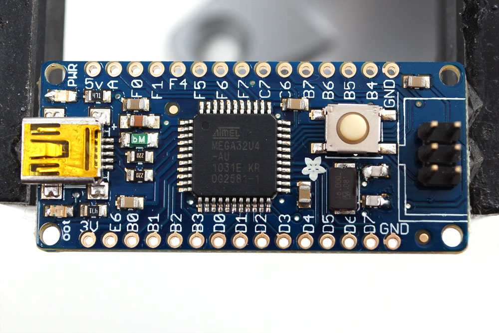
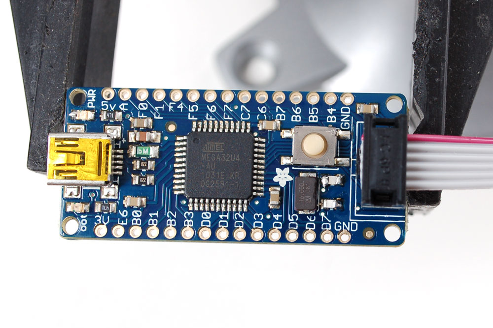
We'll start out easy, by plugging in the atmega32u4 board and installing the driver. For mac and linux users, you can skip this step! If you're using windows, however, you'll need to do this:
Download the **inf** by right-click saving this file and saving it to the Desktop
Then plug a mini-B cable into the board and you should see the LED light up on it and you'll be asked to install the driver.
Select No, not this time:
Select Install from a list or specific location:
Browse to the deskop (or where-ever you saved the inf)
Click Continue Anyways (we didn't pay for Logo testing, but we're using the built in driver so its OK)
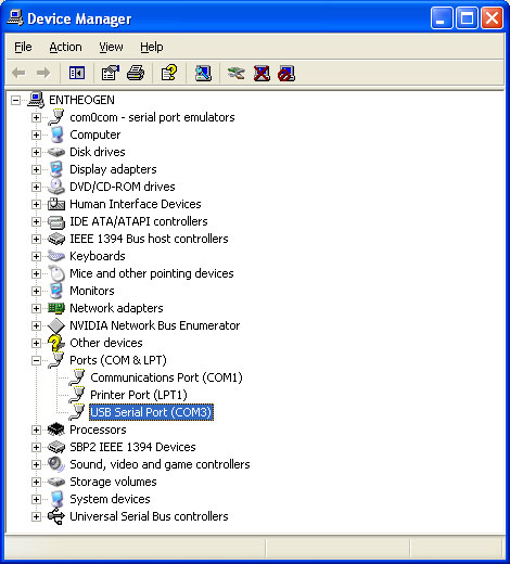
Thats it! The USB-serial port should now show up under the device manager. If you press the reset button it will 'disappear' and reappear.
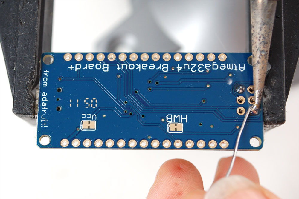
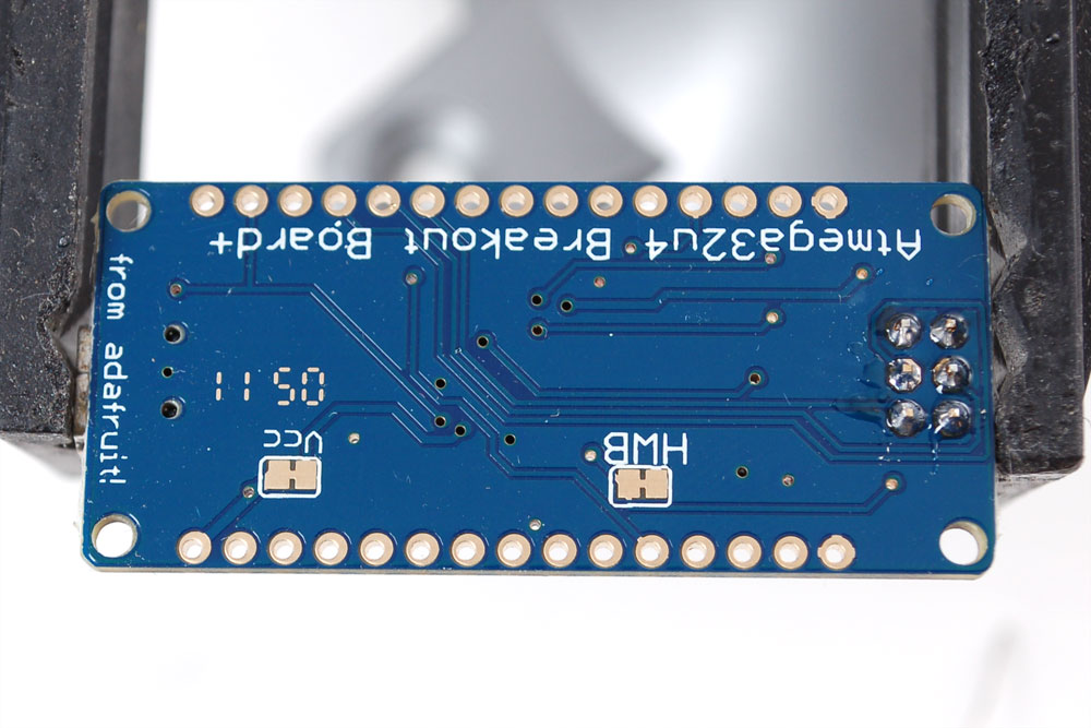
Step 2. Solder 2x3 header to Atmega32u4 board
This step is pretty easy, find the small header piece in the package and solder it into the spot at the end of the Atmega32u4 breakout board. Make sure the short pins are going into the PCB and the long pins are facing up
You may need to use a piece of tape to keep the header in place while soldering it. Solder all 6 pins
Step 3. Cable cut and prep
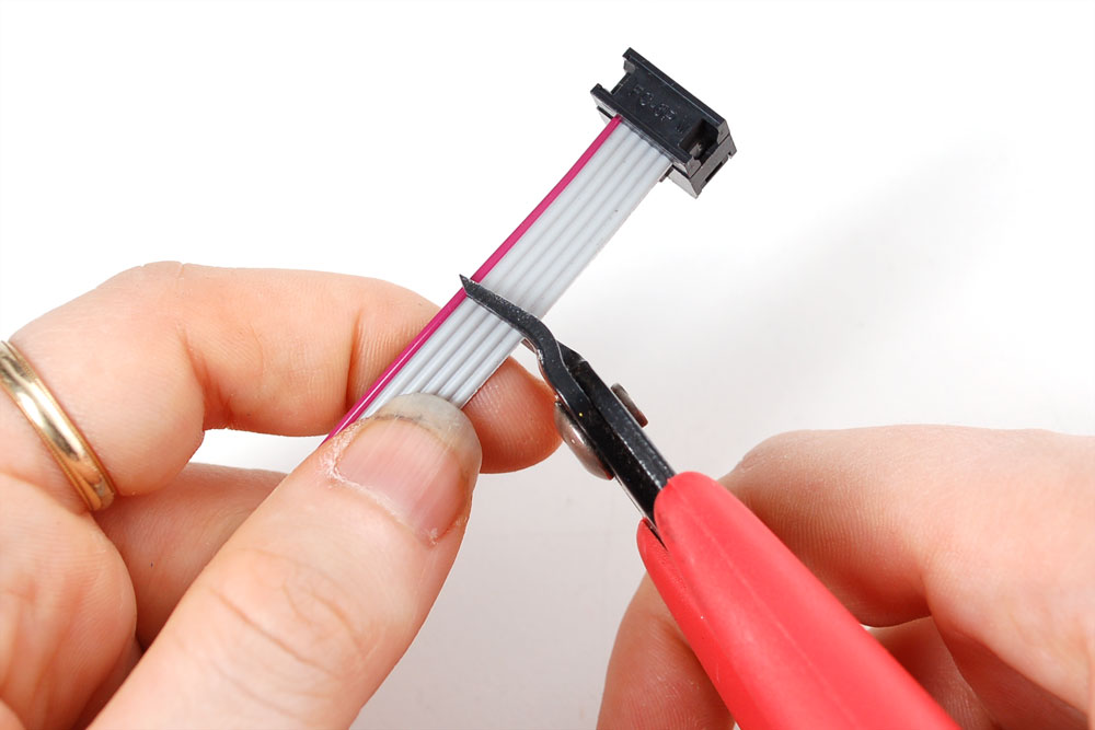
Find the 6-pin IDC cable and plug one end in. it should look like the following. with the cable coming out onto the right side and the red wire up top.
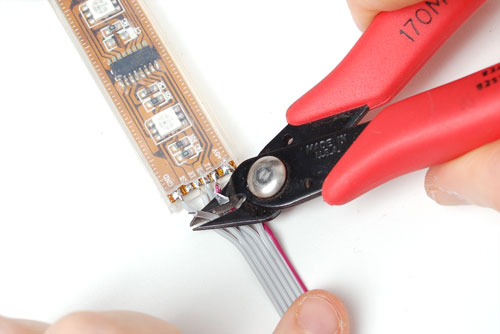
Now cut the other end just before the connector (I'm cutting it about 1" away but don't cut any more off than that!
Disconnect the cable from the board (now that its cut)
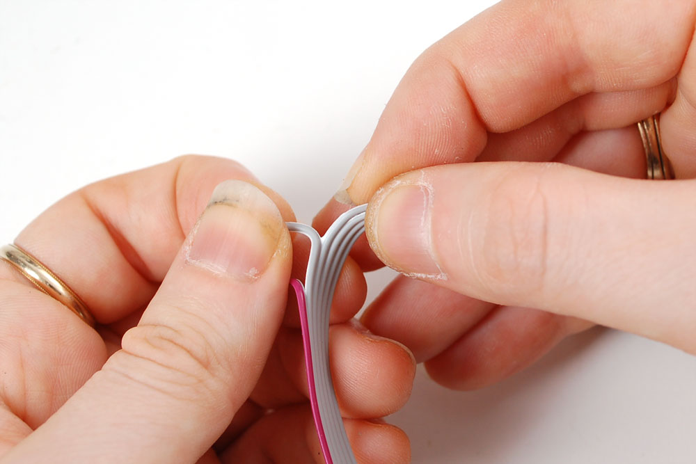
Separate the wires of the cable, you can use fingernails to start, or use the tips of the diagonal cutters to nip into the edges and then pull. Pull them so they are about 1" separated
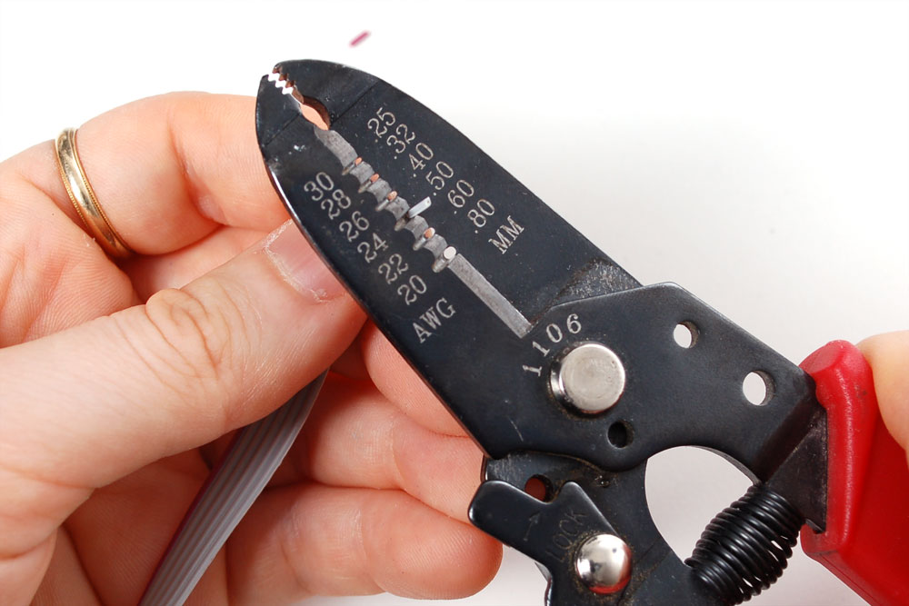
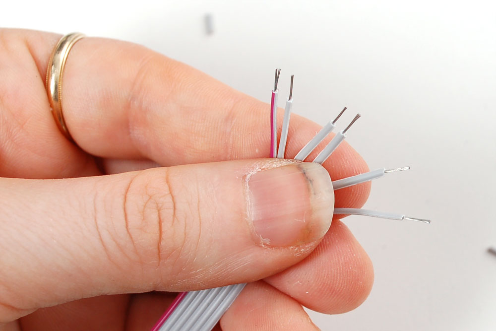
Strip the ends of each of the wires to remove the plastic coating
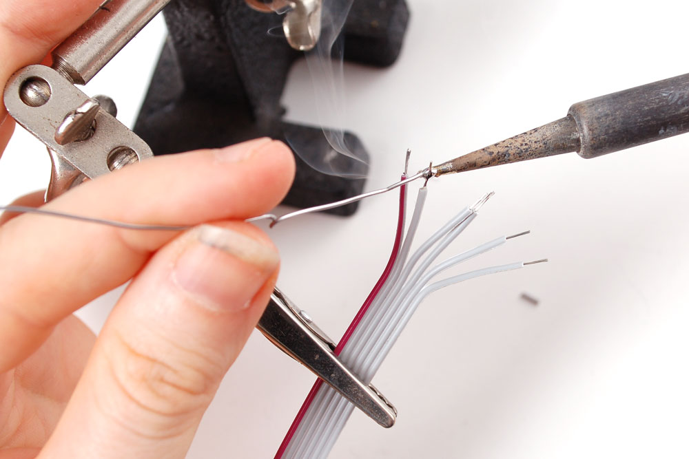
Place the cable in a vise or holder like this third hand tool, and 'tin' the ends by melting solder into the wires while heating with the tip of your soldering iron until they are coated with solder
Step 4. Connect to the LED strip
We have a lot more details on the digital LED strip and how it works here so you may want to also read that stuff.
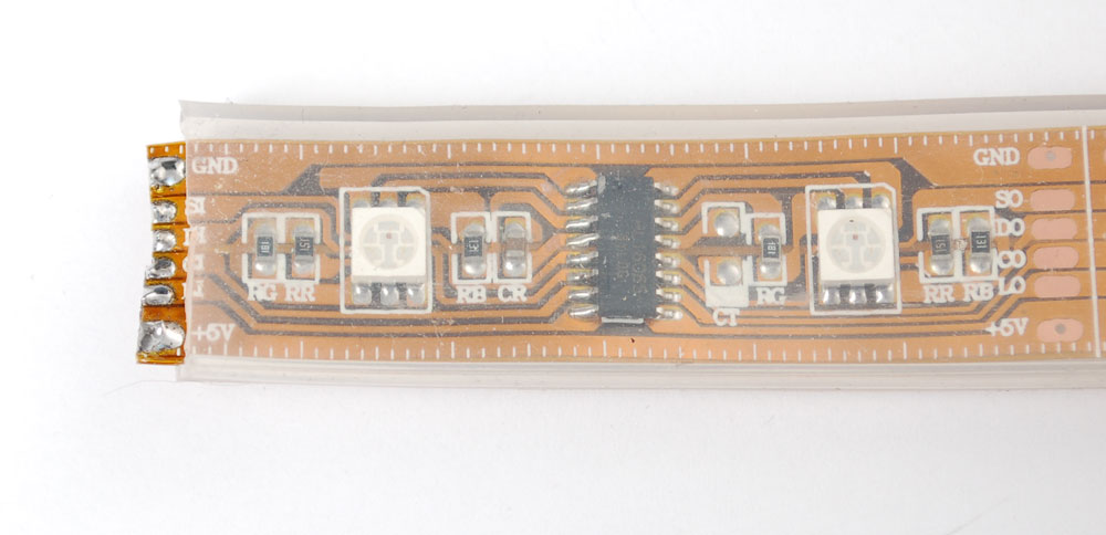
The most important part is that you'll be soldering to one end of the LED strip, and to make sure you are soldering to tbe INPUT end. To determine which is the input, check the writing on the flexible PCB. If it says LI/CI/SI/DI then thats the (correct) input end. If it says LO CO SO DO then thats the (wrong) output. You can only connect to the input end so double check
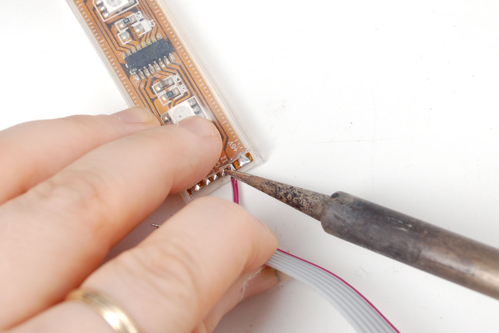
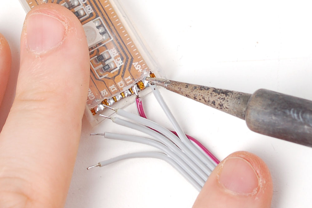
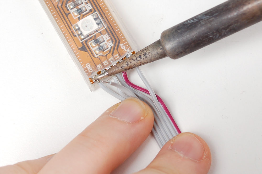
Tin the pads by carefully melting a little solder onto the pads
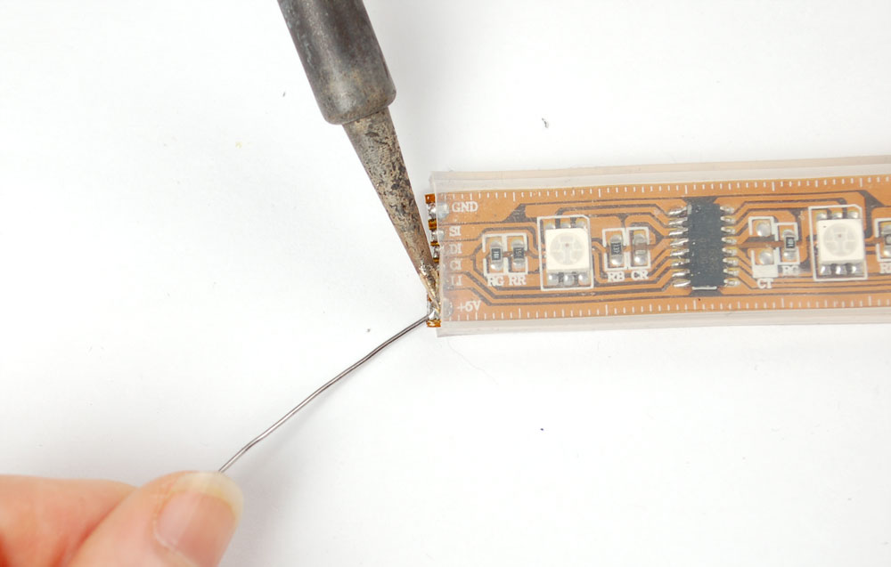
We'll start with the first wire, which is the red-striped one. That wire will connect to the LI pad. Carefully solder the tinned pad to the tinned red wire
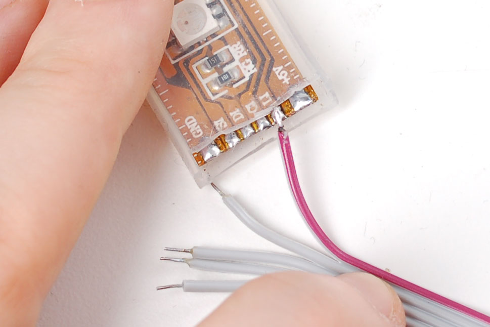
The second wire goes to the right and connects to the +5V power pad
The third wire then goes to the left of LI and connects to CI
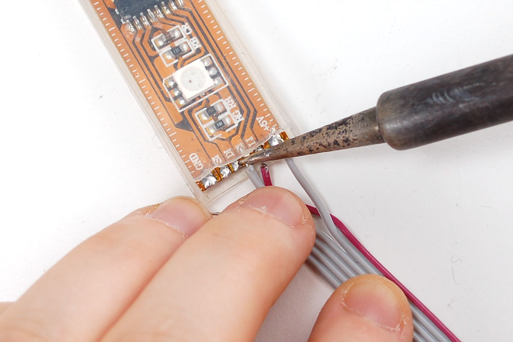
Next wire goes to DI
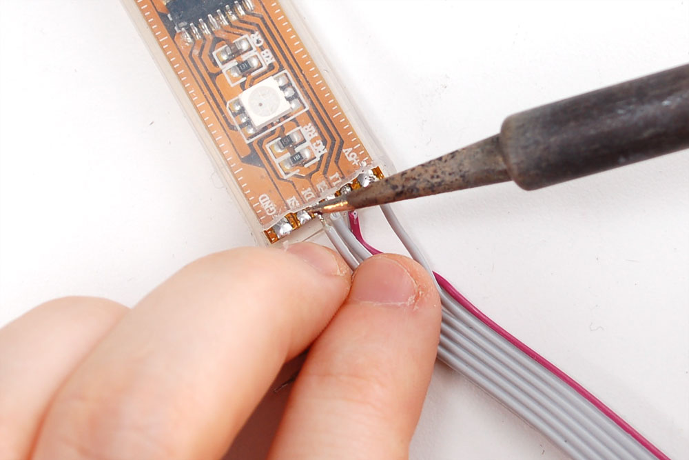
We then skip a wire and go to the last (sixth) wire which connects to GND
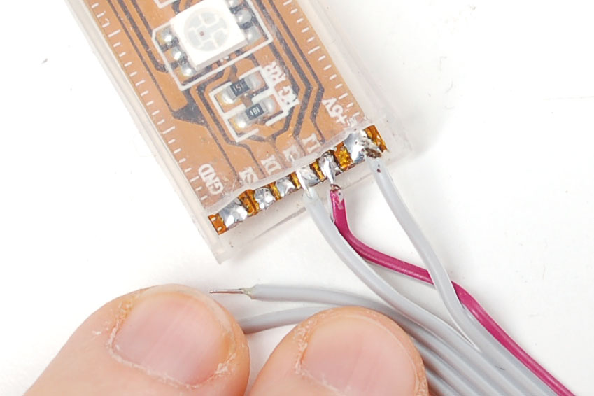
The unused fifth (5th) wire gets trimmed. We wont be connecting to SI so its OK that nothing is soldered to it.
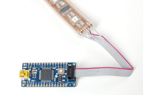
You can now reconnect the cable. Click on the image to enlarge it and make sure your wiring matches!
Step 5. Upload test blinky sketch!
Now its time to get BLINKY!
We'll have to install the Arduino IDE and modify it so that we can use it with this chip. To do this, please visit our detailed instruction page on installing teensyduino and modifying it so it works with the 32u4 board.
Once you've installed the software, come back here.
OK welcome back! Start a new sketch and paste in the follwing
/*
This is the most basic demonstration code of using HL1606-based digital LED strips.
The HL1606 chips are not very 'smart' and do not have built in PWM control. (Although
there is a fading ability, its not that useful)

We have a few examples of using the setLEDcolor() and writeStrip() command that will
allow changing the strip around

public domain
*/


// HL1606strip is an adaptation of LEDstrip from  http://code.google.com/p/ledstrip/
#include "HL1606strip.h"

// for the LED belt, these are the pins used
#define STRIP_D 2
#define STRIP_C 1
#define STRIP_L 3

// Pin S is not really used in this demo since it doesnt use the built in PWM fade
// The last argument is the number of LEDs in the strip. Each chip has 2 LEDs, and the number
// of chips/LEDs per meter varies so make sure to count them! if you have the wrong number
// the strip will act a little strangely, with the end pixels not showing up the way you like
HL1606strip strip = HL1606strip(STRIP_D, STRIP_L, STRIP_C, 32);


void setup(void) {
  // nothing to do!
}

void loop(void) {
   // first argument is the color, second is the delay in milliseconds between commands

   // test all the LED colors with a wipe
   colorWipe(RED, 40);
   colorWipe(YELLOW, 40);
   colorWipe(GREEN, 40);
   colorWipe(TEAL, 40);
   colorWipe(BLUE, 40);
   colorWipe(VIOLET, 40);
   colorWipe(WHITE, 40);
   colorWipe(BLACK, 40);

   // then a chase
   chaseSingle(RED, 40);
   chaseSingle(YELLOW, 40);
   chaseSingle(GREEN, 40);
   chaseSingle(TEAL, 40);
   chaseSingle(VIOLET, 40);
   chaseSingle(WHITE, 40);

   // a colorcycle party!
   rainbowParty(60);
}


/%%**%%%%**%%%%**%%%%**%%%%**%%%%**%%%%**%%%%**%%%%**%%%%**%%%%**%%%%**%%%%**%%%%**%%%%**%%%%**%%%%**%%%%**%%%%**%%%%**%%%%**%%%%**%%%%**%%/

// scroll a rainbow!
void rainbowParty(uint8_t wait) {
  uint8_t i, j;

  for (i=0; i< strip.numLEDs(); i+=6) {
    // initialize strip with 'rainbow' of colors
    strip.setLEDcolor(i, RED);
    strip.setLEDcolor(i+1, YELLOW);
    strip.setLEDcolor(i+2, GREEN);
    strip.setLEDcolor(i+3, TEAL);
    strip.setLEDcolor(i+4, BLUE);
    strip.setLEDcolor(i+5, VIOLET);

  }
  strip.writeStrip();

  for (j=0; j < strip.numLEDs(); j++) {

    // now set every LED to the *next* LED color (cycling)
    uint8_t savedcolor = strip.getLEDcolor(0);
    for (i=1; i < strip.numLEDs(); i++) {
      strip.setLEDcolor(i-1, strip.getLEDcolor(i));  // move the color back one.
    }
    // cycle the first LED back to the last one
    strip.setLEDcolor(strip.numLEDs()-1, savedcolor);
    strip.writeStrip();
    delay(wait);
  }
}


// turn everything off (fill with BLACK)
void stripOff(void) {
  // turn all LEDs off!
  for (uint8_t i=0; i < strip.numLEDs(); i++) {
      strip.setLEDcolor(i, BLACK);
  }
  strip.writeStrip();
}

// have one LED 'chase' around the strip
void chaseSingle(uint8_t color, uint8_t wait) {
  uint8_t i;

  // turn everything off
  for (i=0; i< strip.numLEDs(); i++) {
    strip.setLEDcolor(i, BLACK);
  }

  for (i=0; i < strip.numLEDs(); i++) {
    strip.setLEDcolor(i, color);
    if (i != 0) {
      // make the LED right before this one OFF
      strip.setLEDcolor(i-1, BLACK);
    }
    strip.writeStrip();
    delay(wait);
  }
  // turn off the last LED before leaving
  strip.setLEDcolor(strip.numLEDs() - 1, BLACK);
}

// fill the entire strip, with a delay between each pixel for a 'wipe' effect
void colorWipe(uint8_t color, uint8_t wait) {
  uint8_t i;

  for (i=0; i < strip.numLEDs(); i++) {
      strip.setLEDcolor(i, color);
      strip.writeStrip();
      delay(wait);
  }
}
Be sure to selectthe Atmega32u4 board. Also select the Serial Port that is made when you plug in the Atmega32u4 board to USB and press the reset button.
If you've already uploaded something to the board, you might have to press the reset button to enter the bootloader (the green led will be pulsing), then check the Serial Port menu again.
If uploading goes well, you should see the following:
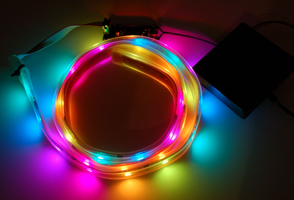
Once you've uploaded you should see the LED belt perform the blinky test!
<object type="application/x-shockwave-flash" width="400" height="225" data="http://www.flickr.com/apps/video/stewart.swf?v=71377" classid="clsid:D27CDB6E-AE6D-11cf-96B8-444553540000"> </object>
Step 6. Battery packprotection diode
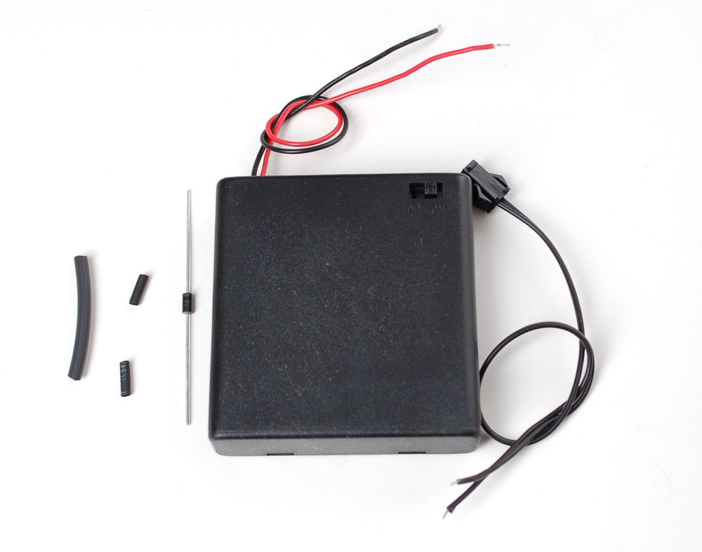
Now we can work on making the battery pack to give us portable power. Grab the remaining parts you'll need, the battery holder, diode, long battery connection cable, and small heatshrink
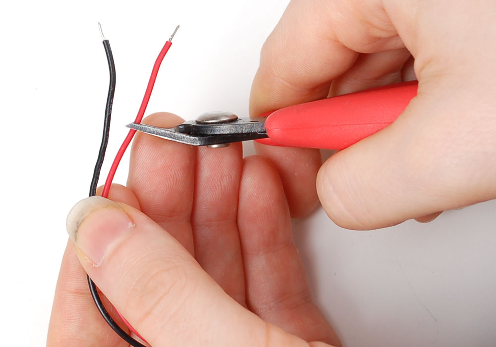
Cut the red wire of the battery pack short by about an inch
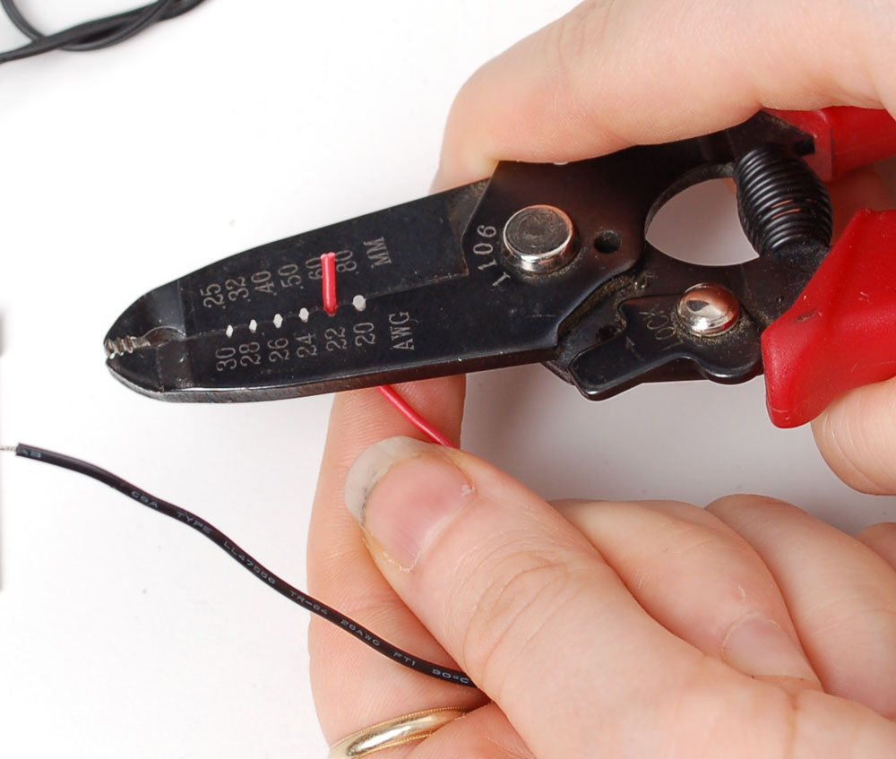
Then strip and tin the wire
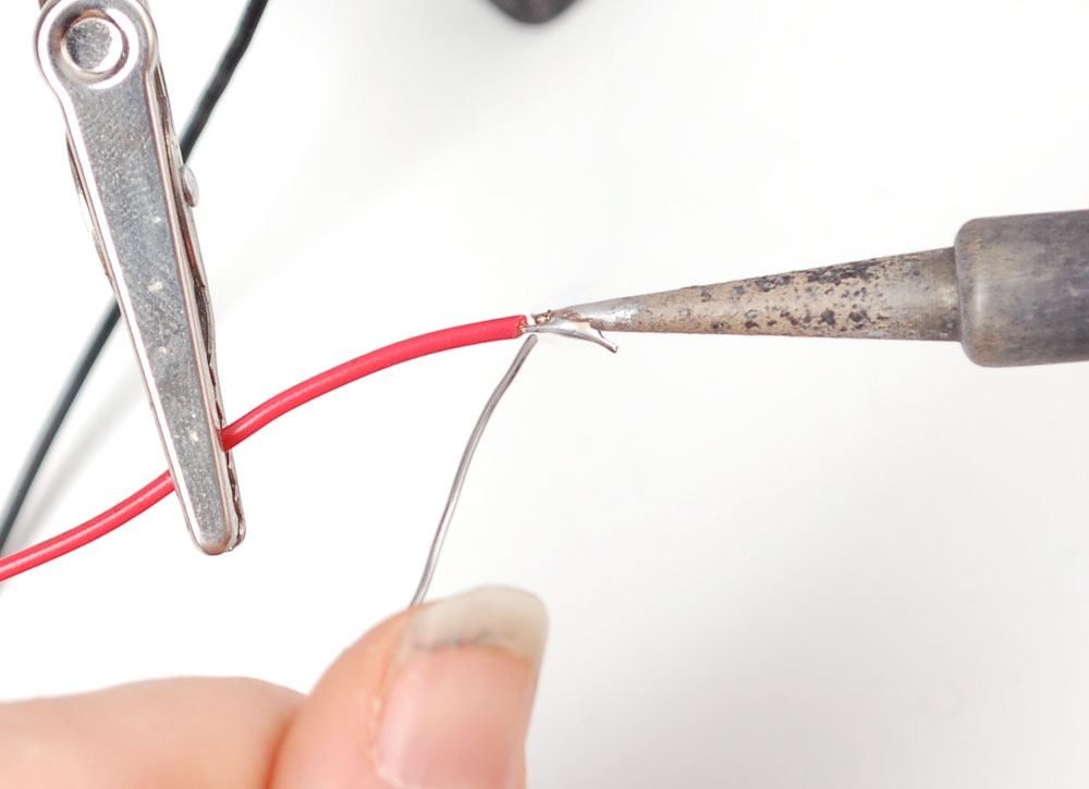
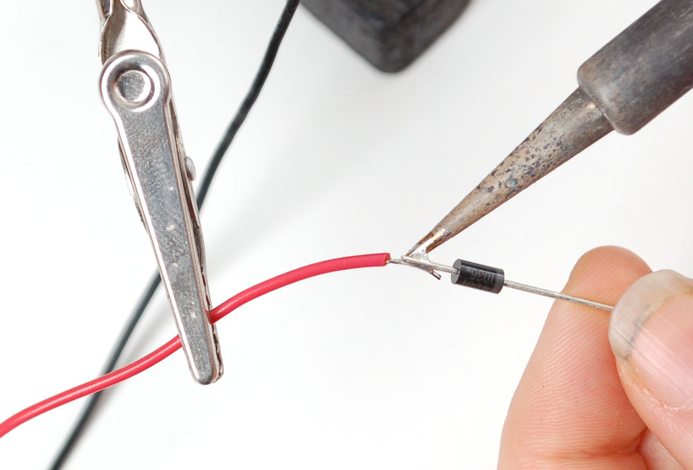
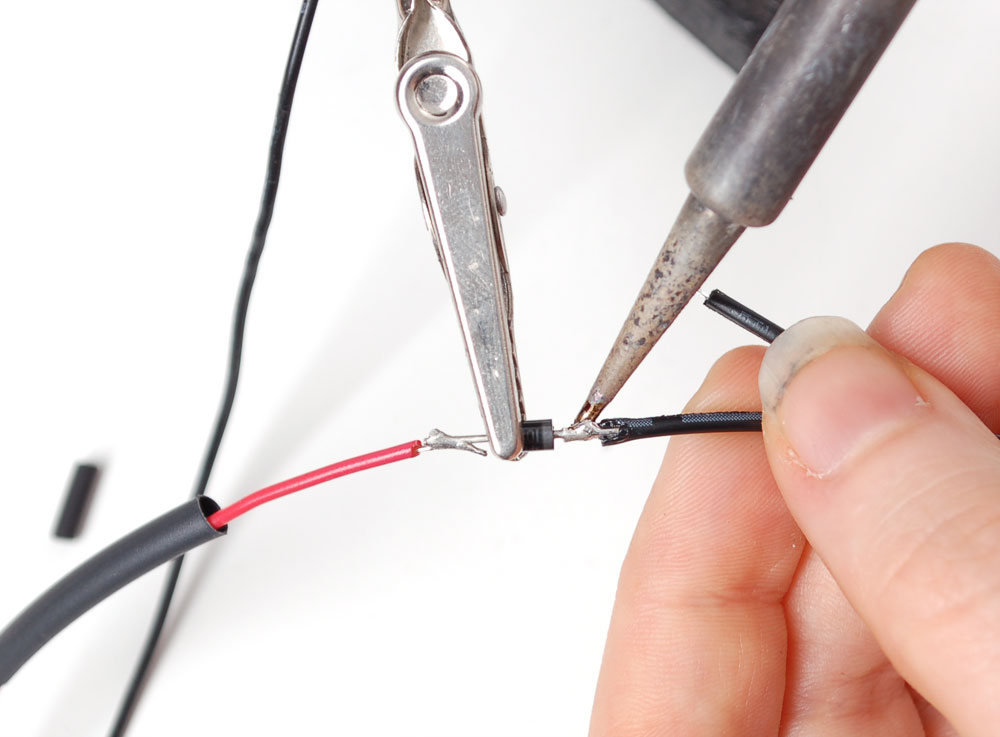
Find the diode, this part will protect the board in case you put the batteries in backwards, it also lowers the voltage a little so if you have fresh alkaline batteries, the voltage won't be too high. Diodes are directional so make sure you're working with the right end. Find the end that doesn't have a white strip and cut it short. Solder that end to the red wire
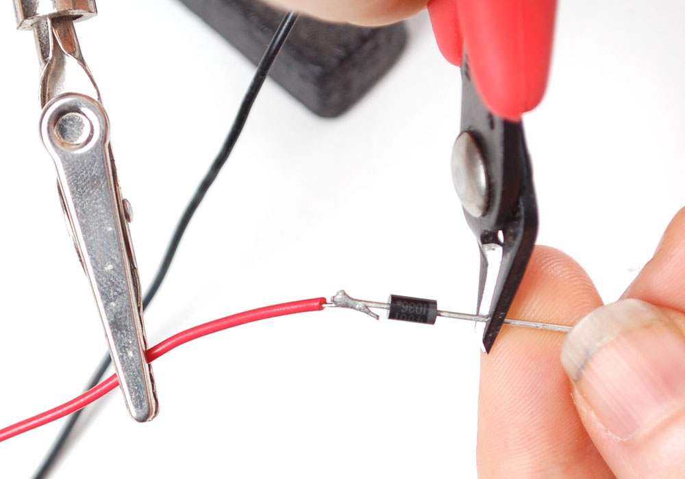
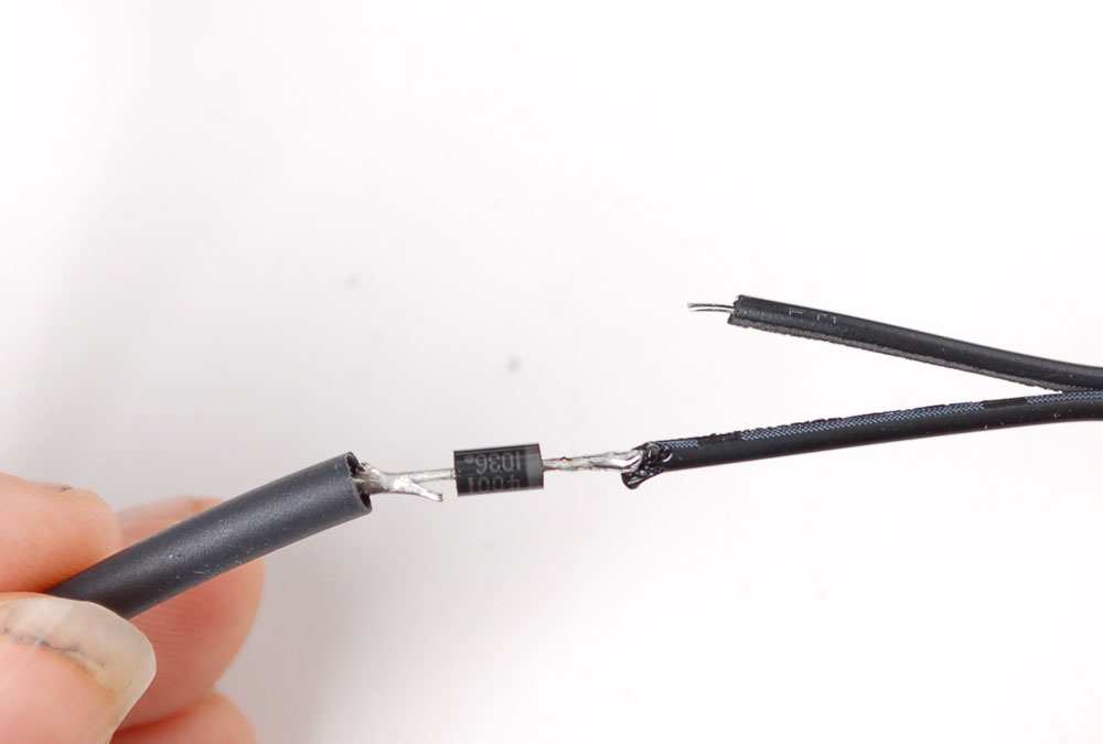
Clip the other side (the side with a white stripe)
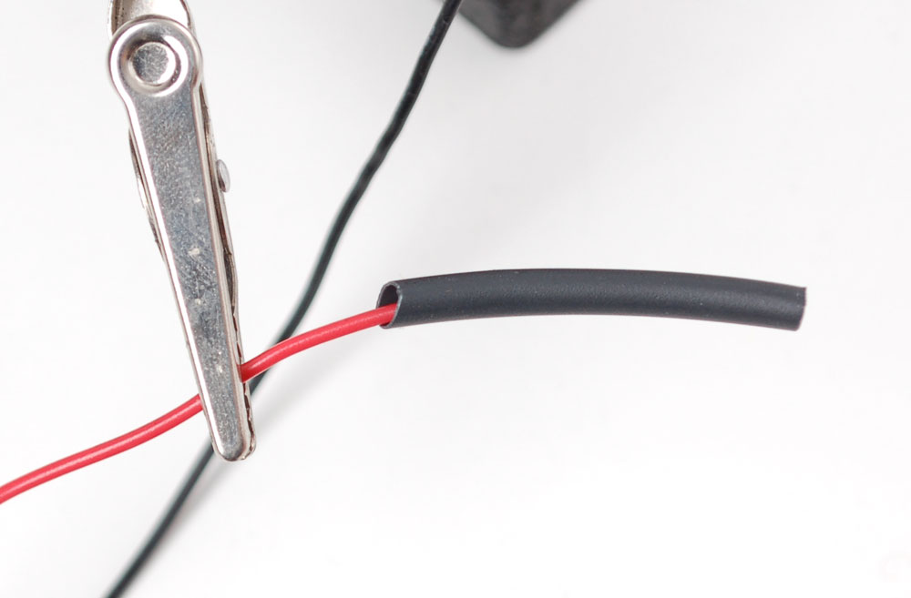
Cut off and slide a ~2" piece of black heatshrink onto the red wire past the diode
Now solder one wire from the battery connection cable onto the other end of the diode, you may need to tin both if you are having trouble getting a good joint. It doesn't matter which wire you choose so just pick one!
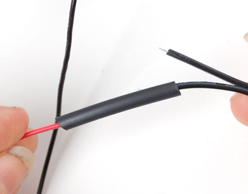
Slide the heatshrink back over the diode and solder joints
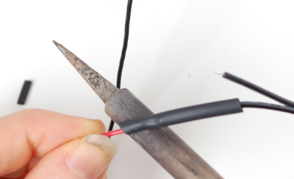
Now shrink the tubing to protect the diode, you can use a hair dryer, heat gun, lighter or the edge of your soldering iron.
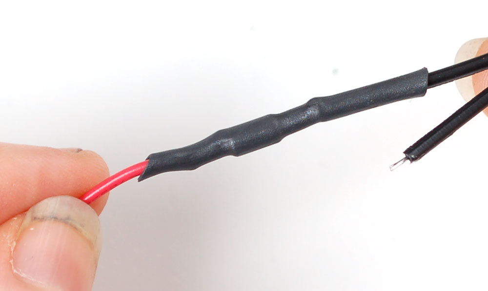
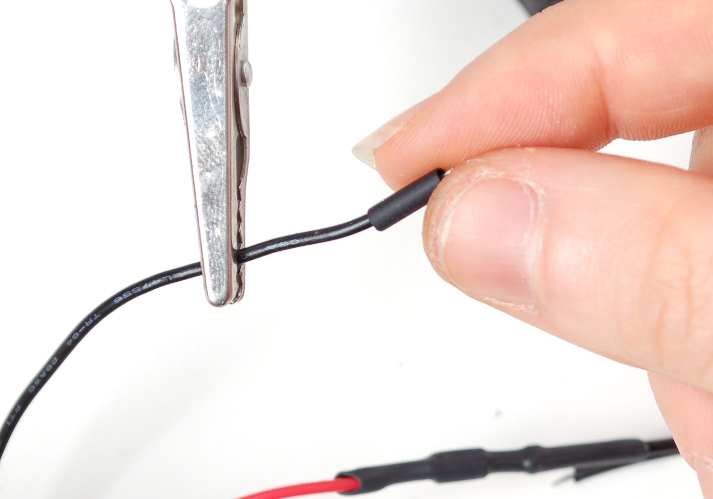
Now we'll connect the other side of the long power cable to the black wire. Slide a small 1" piece of heat shrink onto the black wire (this image shows a much shorter piece, but its too short so go a little longer)
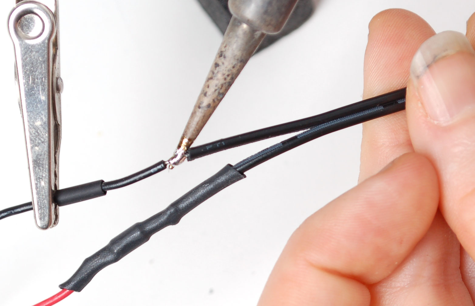
…and solder together the wires
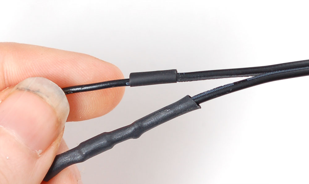
Then heatshrink like you did before!
Step 7. Power connection
Now we will do the other half of the power connection, the side that connects to the board.
Plug the matching shorter power cable into the longer one so they snap together (they can only go one way)
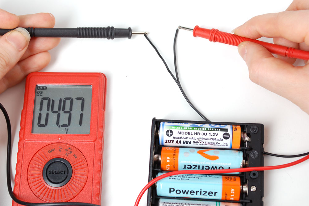
Now you'll want to trace the red power wire back through the connectors. We suggest using a multimeter to be sure. Put 4 AA's in the holder and turn it on. Then use a multimeter to measure the voltage between the cable wires. One way will be about -5V and the other will be +5V. When it's reading +5V the red handle is touching the positive wire. In this example, its the one on the right:
Turn off the power pack (or remove the batteries)
Cut the positive wire short by about 1"
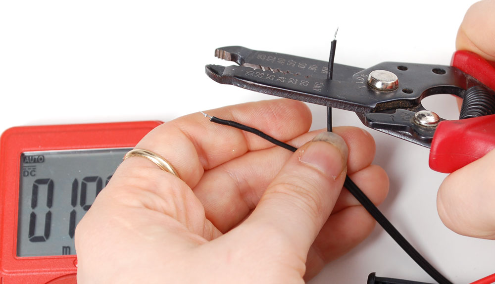
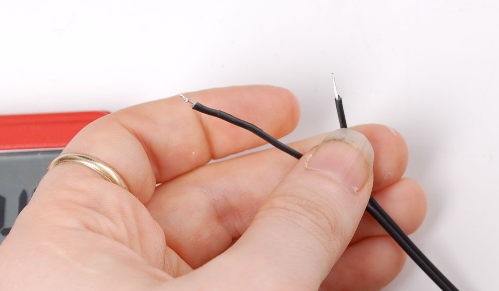
Strip and tin the wire
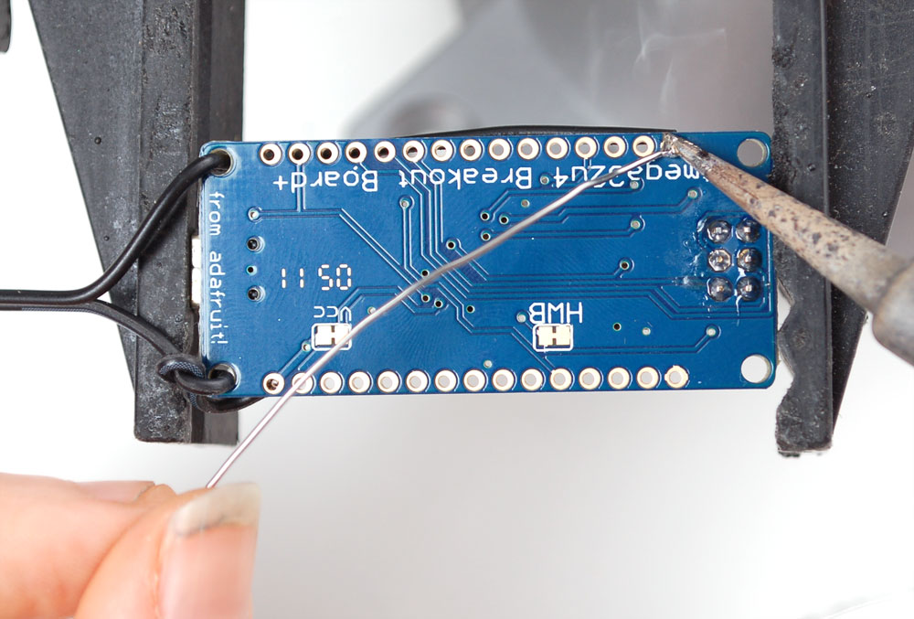
Thread the shorter positive wire into the top left hole and knot it. The longer negative wire goes through the opposite (bottom left) hole.
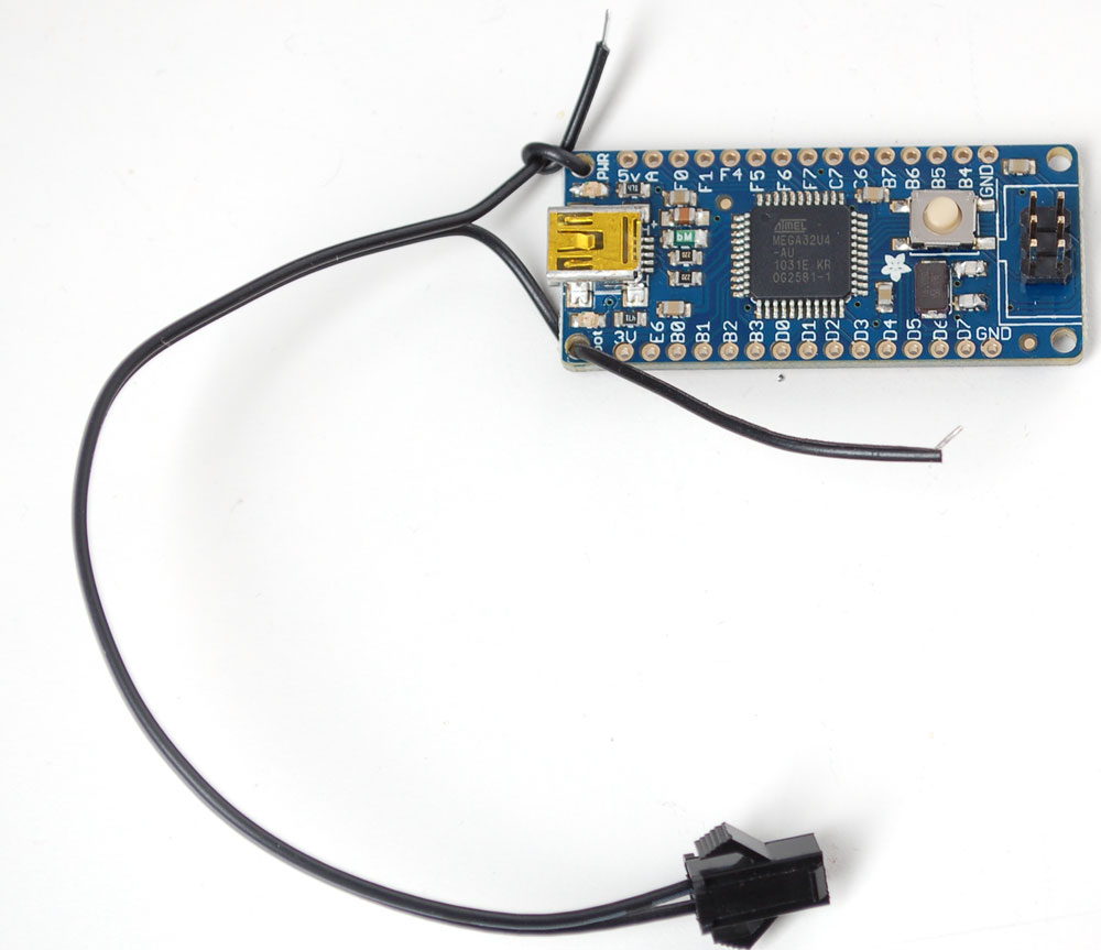
Pull the wires through so that you can push the negative wire into the GND pad all the way to the right.

The positive wire goes to the first 5V pad right next to the hole, all the way to the top left in the image above.
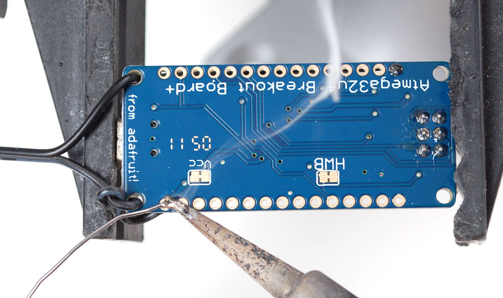
Turn the board over, and solder the ground wire
…and the +5V wire.
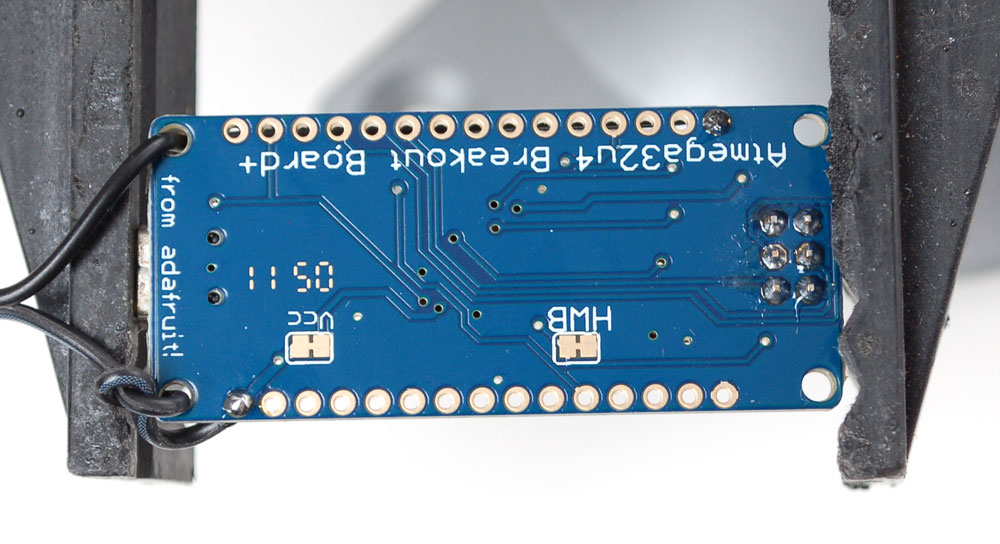
Check your work before we finish up!
Step 8. Finishing up
Connect the LED strip back to the microcontroller board, and place the batteries back into the pack.
Turn on the pack and wait a few seconds, you should see the LED pattern again!
Now we'll wrap it up by protecting the cable that goes to the end of the strip
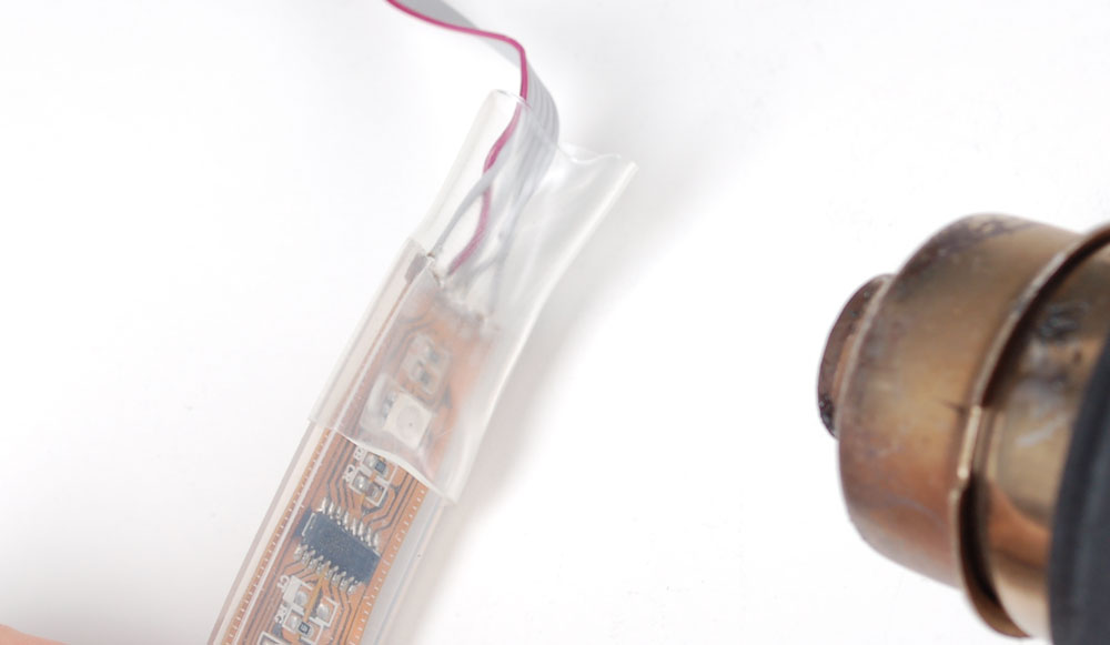
Slide the large heatshrink onto the end of the LED strip
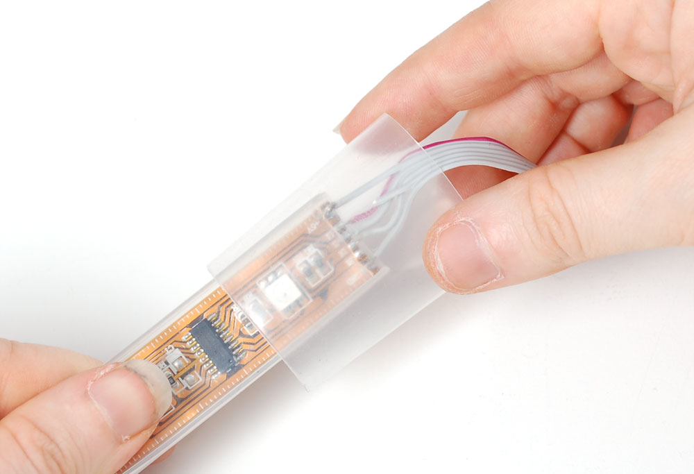
Use a heat gun, hair drier or lighter to shrink it down.
While its warm (but not too hot, be careful!) wrap the cable tie around the end of the heatshrink
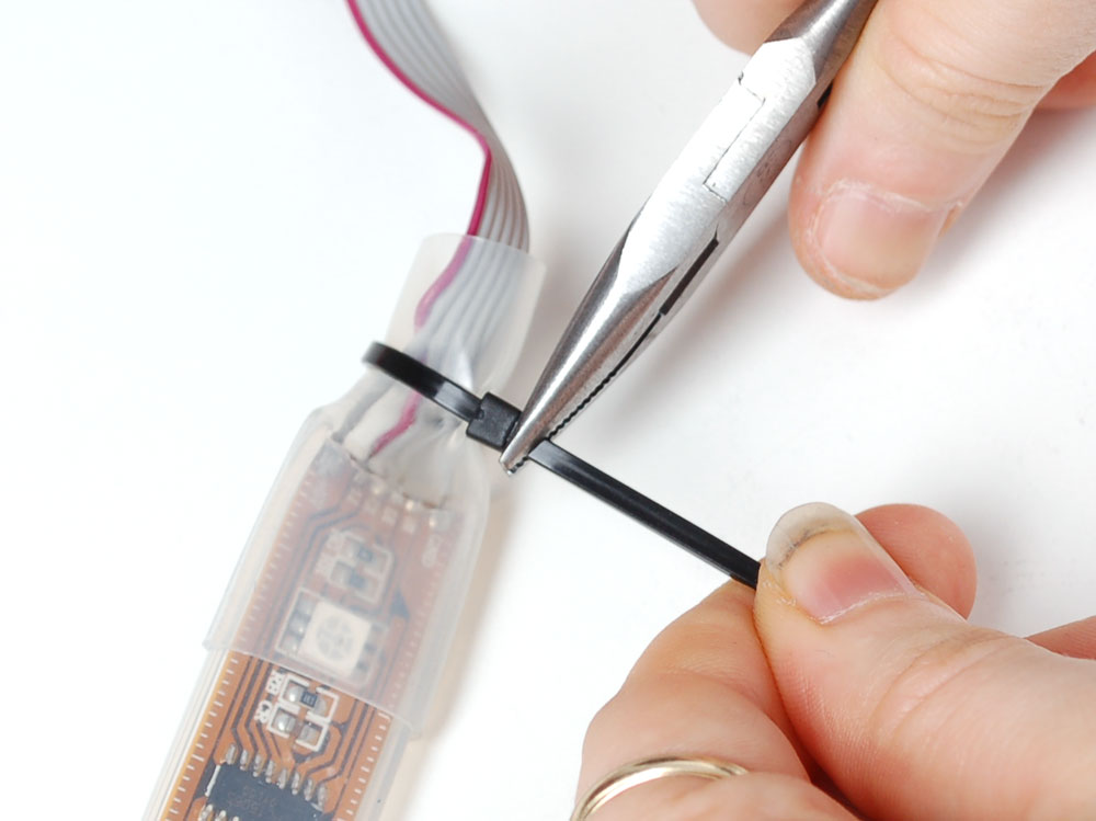
Tighten it over the IDC cable, and cut the end.
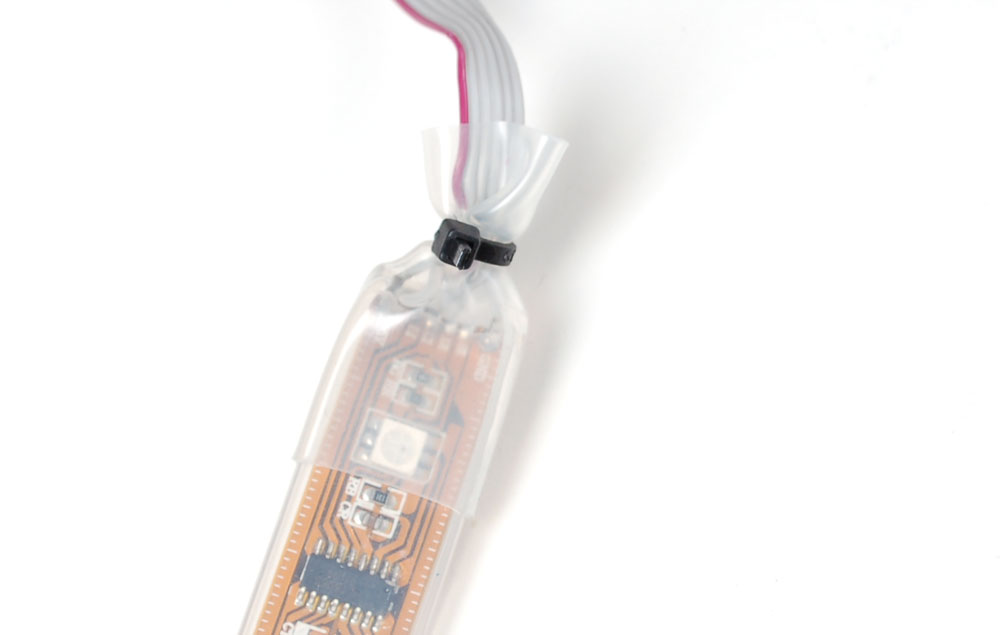
That's it! Now the project is done. You can keep the battery pack and microcontroller board in your pocket and wrap the belt around you
