This is an old revision of the document!
Table of Contents
LED full color (RGB) Pixels!
RGB Pixels are digitally-controllable lights you can set to any color, or animate. Each metal pixel contains 4 RGB LEDs and a controller chip soldered to a PCB. The pixel is then 'flooded' with epoxy to make it waterproof. These are fairly large pixels but they have a lot of nice mounting options, such as two metal flanges on the side and a 0.15"/4mm diameter hole in the middle so you can screw them directly onto a surface. They're typically used to make outdoor signs. Compared to our other LED dots, these are much bigger and much brighter, good for larger scale installations.
Basic stats
- 36mm square waterproof pixels
- Approximately 3 inches (75mm) apart on 4-pin strand
- 12 Volts DC, 120 milliamps max per pixel (all LEDs on, full white)
- WS2801 LED driver chip provides 24-bit color: Datasheet
- 2-pin SPI-like protocol — easy for Arduino and other microcontrollers
You can pick up RGB pixels in strands of 20 from the Adafruit shop.
Here is a basic video showing some 36mm pixels running a test pattern:
Project Ideas
These pixels could be used for stuff like…
LED coffee tables (this one is 'hand made' but you could skip the wiring/drivers part and just use a long strand of our LED pixels now)
Signs or displays:
A matrix or video wall can also be created, like a giant version of our Adavision kit seen here:
Overview
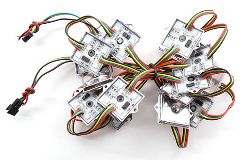
Our 36mm square pixels are our biggest and brightest! They feature four LEDs total and come in a flat metal square 'plate' that is flooded with epoxy. They require 12VDC power and can draw up to 120mA per pixel (there are two sets of two RGB LEDs connected in parallel, each drawing 60mA at 12VDC).
![]()
The LED pixels are spaced along a strand of ribbon cable, with about 3 inches or 75mm between pixels. If additional distance is needed you can cut the ribbon cable and solder 4 wires to extend the gap to the desired length.
Powering 36mm Pixels
An important part of running a lot of LEDs is to keep track of power usage. Individual LEDs don't get very hot or use tons of power, but they add up fast!
Each single 36mm RGB LED pixel can draw up to 120mA from a 12V supply. That means a strand of 20 can use up to 2.4 Amps. Of course this is assuming all the LEDs are on. If you keep most of the LEDs off (by color swirling or patterns) the power usage can be 1/3 this or less.
We suggest a nice switching supply for driving LED pixels, such as our 12 Volt 5 Amp supply. For larger projects, a slightly modified ATX computer power supply can provide 10 Amps to power upwards of 80 pixels!
Since the 36mm pixels are powered by 12V but use 3-5V signaling, make sure you don't accidentally connect the 12V to your microcontroller — this will destroy it! For that reason, the power lines are separated out. Use something like a 2.1mm DC terminal block adapter so that you can directly plug in our 12V adapter.
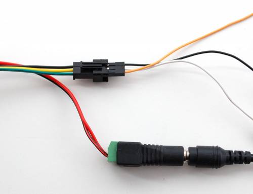
The wires on the 3-JST SM connector are then connected to your microcontroller: black is ground, yellow is data and green is clock.
Driver Chip
Each pixel contains a small microchip within the silicone dot. The WS2801 LED driver chip is custom designed for this purpose. These chips are very simple to communicate with — all they do is shift color data in from one pin and out another. To issue data from a microcontroller such as an Arduino, one "shifts out" 24 bits of color information — the first data out corresponds to the pixel closest to the microcontroller. To write data to 10 LEDs, you would issue 240 bits (10 * 24). Following the data, a 500 microsecond pause will "latch" the data and show the new LED colors.
The WS2801 chip is the same as in our 12mm pixels, so any software that works with the smaller pixels can also control these larger versions!
Wiring
The nice thing about these pixels is that they are digitally controlled. That is, even though there are only two data lines (clock/data inputs), you can put as many pixels as you'd like in a row and each one is controllable.
It is important to note that even though it looks like the 4-conductor ribbon is continuous, it isn't! The ground and 5V lines are shared but the two data input pins go to a microcontroller and the other side has two data outputs.
![]()
When connecting to a microcontroller make sure you are connecting the input pins to the microcontroller! Best way to tell is to look at the dots and find the arrow. In the large dots above, the arrow is in the top right corner. The inputs are on the left and the signal passes to the right. If you want to connect multiple strands together, make sure input goes to output.
Wiring is pretty easy since there are only 4 wires. The only important thing is that unless you are sure you will be using only a few of the LEDs at a time, you should not try to power the strip from the 5V on the Arduino. The Arduino is only mean to drive about 500mA of current, and as we saw earlier, a strand can take 1000mA or more if on! For that reason, we suggest powering with an external regulated 5V supply.
For LPD6803 Pixels, use this diagram with Red going to +5, Green going to digital 3, Yellow going to digital 2 and Blue going to Ground. WS2801 wire colors will be different, see below!
Just make sure to 'share' the ground pin, and triple check that you have the voltage polarity right so that ground is 0V and power is 5V. For the arduino library we wrote, you can use any two pins.
Extra special note for WS2801 pixels
PLEASE NOTE: THE WIRE COLORS SOMETIMES CHANGE FROM BATCH TO BATCH! Do not assume the wire colors are 'logical' or the same for each strand. Double check by looking at the first input pixel!
If you have 12mm pixels you may have newer WS2801 or older LPD6803 pixels. You should check the pixel to verify what chip is inside. This is pretty easy, for the WS2801's you'll see it written on the PCB. You can also check your kit packaging.
![]()
Here you can see the WS2801 written on the PCB. Another really annoying thing is that like we mentioned, the wire colors for the WS2801 pixels can be 'non-intuitive'. For example the first batch of WS2801 we got had Data wire blue, Clock wire red, Ground wire white, and 5V wire black. You can determine the wiring for sure by holding up the pixel as shown in that photo and noting that the wire order is Data, Clock, Ground, +5V (this is not the same as LPD6803, see the diagram above for LPD6803 wiring!) Sorry about that!
Code!
LPD6803 pixels
The code to drive these dots is fairly simple, except that the PWM pin and the data clock pin is shared which means that you can't just stick the PWM pin on a hardware timer output because then its not possible to use it for the data clocking.
Instead, the library uses an interrupt that goes off every few milliseconds. If there is data to be updated on the strip, it sends that data. If not, it just pulses pin to keep the PWM going.
Note that the interrupt uses timer 1 which means the pin 9 and 10 PWMs will not 'work' for servos, please use a 'software servo' library!
This code is heavily based off of bliptronics' original code except we library-ized it and trimmed it down. You can download the library from github, then follow our library installtion procedure.
Once you've rebooted, load up the strandtest.pde example sketch, we'll go through the most important parts.
First up, you'll need to make an library object to talk to the strip. It is initialized with three variables, the number of pixels and the data/clock pin. You can change these later.
// Set the first variable to the NUMBER of pixels. 20 = 20 pixels in a row
LPD6803 strip = LPD6803(20, dataPin, clockPin);
Next we will set up the strip in the setup() procedure.
void setup() {
  // The Arduino needs to clock out the data to the pixels
  // this happens in interrupt timer 1, we can change how often
  // to call the interrupt. setting CPUmax to 100 will take nearly all all the
  // time to do the pixel updates and a nicer/faster display,
  // especially with strands of over 100 dots.
  // (Note that the max is 'pessimistic', its probably 10% or 20% less in reality)
  strip.setCPUmax(50);  // start with 50% CPU usage. up this if the strand flickers or is slow

  // Start up the LED counter
  strip.begin();

  // Update the strip, to start they are all 'off'
  strip.show();
}
setCPUmax() configures the timer 1 interrupt that PWM's the strand. You can change this from 0 to 100, it runs in the background. The 'max' is calculated assuming the longest possible timing (when sending data) so its a big pessimistic. 50% should be plenty, you can mess with this to make the strip more or less 'flickery' You can change this 'on the fly' so for example set it to 0% just before doing a bunch of Ethernet stuff, then back to 50% later.
begin() actually starts the interrupt
show() is what updates the strand display. You'll need to call it after setting any colors to see the updates. This way you can change the entire strip at a time (it takes the same amount of time to change one pixel as it does for an entire strip because the full strip data must be shifted out at once)
Last, we'll look at an example function, colorWipe. This creates a 'chase' that fills the strip up with a color. It is basically a loop that increments through every pixel (which you can conveniently get by numPixels() ) and sets the pixel color of that pixel (incremented with i) to the color c. In this case the color is stored in a 16 bit variable. The strip output is then updated with show(). Finally there is some delay (otherwise this would happen instantly)
Below that is a little helper that takes 8 bit red green and blue and bit-mashes them into a 15 bit color. This means that the 'max' value for each color is 31.
// fill the dots one after the other with said color
// good for testing purposes
void colorWipe(uint16_t c, uint8_t wait) {
  int i;

  for (i=0; i < strip.numPixels(); i++) {
      strip.setPixelColor(i, c);
      strip.show();
      delay(wait);
  }
}

/* Helper functions */

// Create a 15 bit color value from R,G,B
unsigned int Color(byte r, byte g, byte b)
{
  //Take the lowest 5 bits of each value and append them end to end
  return( ((unsigned int)g & 0x1F )<<10 | ((unsigned int)b & 0x1F)<<5 | (unsigned int)r & 0x1F);
}
For example, in the loop() we call colorWipe(Color(31, 0, 0), 50) which will fill the strand with only-full-red light, pausing about 50 milliseconds between pixels.
  colorWipe(Color(31, 0, 0), 50);  // red fill
  colorWipe(Color(0, 31, 0), 50);  // green fill
  colorWipe(Color(0, 0, 31), 50);  // blue fill
WS2801 pixels
This code is very similar to the LPD6803 but simpler because we do not need to use the CPU to update the pixel clock constantly.
The code to drive these dots is even simpler, you don't need to worry about any timers, use any two pins you'd like! You can use anything that requires timer 1 like the servo libraries.
To download, visit the repository on Github. Click the DOWNLOADS button in the top right corner, rename the uncompressed folder WS2801. Check that the WS2801 folder contains WS2801.cpp and WS2801.h
Place the WS2801 library folder your <arduinosketchfolder>/libraries/ folder. You may need to create the libraries subfolder if its your first library. Restart the IDE. We also have a tutorial on library installation
Once you've rebooted, load up the WS2801→strandtest.pde example sketch, we'll go through the most important parts.
First up, you'll need to make an library object to talk to the strip. It is initialized with three variables, the number of pixels and the data/clock pin. You can change these later.
// Set the first variable to the NUMBER of pixels. 25 = 25 pixels in a row
WS2801 strip = WS2801(25, dataPin, clockPin);
Next we will set up the strip in the setup() procedure.
void setup() {
  // Start up the LED counter
  strip.begin();

  // Update the strip, to start they are all 'off'
  strip.show();
}
begin() initializes the library and sets all the pixel colors to off.
show() is what updates the strand display. You'll need to call it after setting any colors to see the updates. This way you can change the entire strip at a time (it takes the same amount of time to change one pixel as it does for an entire strip because the full strip data must be shifted out at once)
Last, we'll look at an example function, colorWipe. This creates a 'chase' that fills the strip up with a color. It is basically a loop that increments through every pixel (which you can conveniently get by numPixels() ) and sets the pixel color of that pixel (incremented with i) to the color c. In this case the color is stored in a 32 bit variable but uses only the bottom 24 bits. The strip output is then updated with show(). Finally there is some delay (otherwise this would happen instantly)
Below that is a little helper that takes 8 bit red green and blue and bit-mashes them into a 24 bit color. This means that the 'max' value for each color is 255.
// fill the dots one after the other with said color
// good for testing purposes
void colorWipe(uint32_t c, uint8_t wait) {
  int i;

  for (i=0; i < strip.numPixels(); i++) {
      strip.setPixelColor(i, c);
      strip.show();
      delay(wait);
  }
}

/* Helper functions */
// Create a 24 bit color value from R,G,B
uint32_t Color(byte r, byte g, byte b)
{
  uint32_t c;
  c = r;
  c <<= 8;
  c |= g;
  c <<= 8;
  c |= b;
  return c;
}
For example, in the loop() we call colorWipe(Color(255, 0, 0), 50) which will fill the strand with only-full-red light, pausing about 50 milliseconds between pixels.
  colorWipe(Color(255, 0, 0), 50);  // red fill
  colorWipe(Color(0, 255, 0), 50);  // green fill
  colorWipe(Color(0, 0, 255), 50);  // blue fill
Download
LPD8603 library
We have an Arduino lirbary that can be fairly easily ported to any microcontroller with two digital output pins and a interrupt timer. This code is heavily based off of bliptronics' original code except we library-ized it and trimmed it down.
You can download the library from github, then follow our library installation procedure.
Dont forget that this library uses an interrupt on timer 1 which means the pin 9 and 10 PWMs will not 'work' for servos, please use a 'software servo' library!
WS2801 library
To download, visit the repository on Github. Click the DOWNLOADS button in the top right corner, rename the uncompressed folder WS2801. Check that the WS2801 folder contains WS2801.cpp and WS2801.h
Place the WS2801 library folder your <arduinosketchfolder>/libraries/ folder. You may need to create the libraries subfolder if its your first library. Restart the IDE. We also have a tutorial on library installation
