
The first step is to solder the kit together. If you've never soldered before, check the tutorials on the preparation page
Some web browsers (basically, IE) do not like my website so much and load the photonotes slowly. So, if you are wondering where the rest of the instructions are, either wait a while and IE will eventually display it (below here). Or download Firefox/Safari which does not have this problem!
|
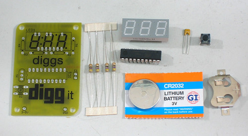
Check the kit to verify you have all the parts necessary |
|
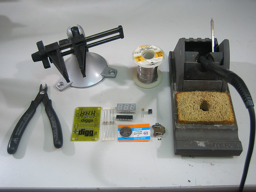
Get your space set up with a good light, a vice or "third-hand" tool, diagonal cutters, and a soldering iron/solder |
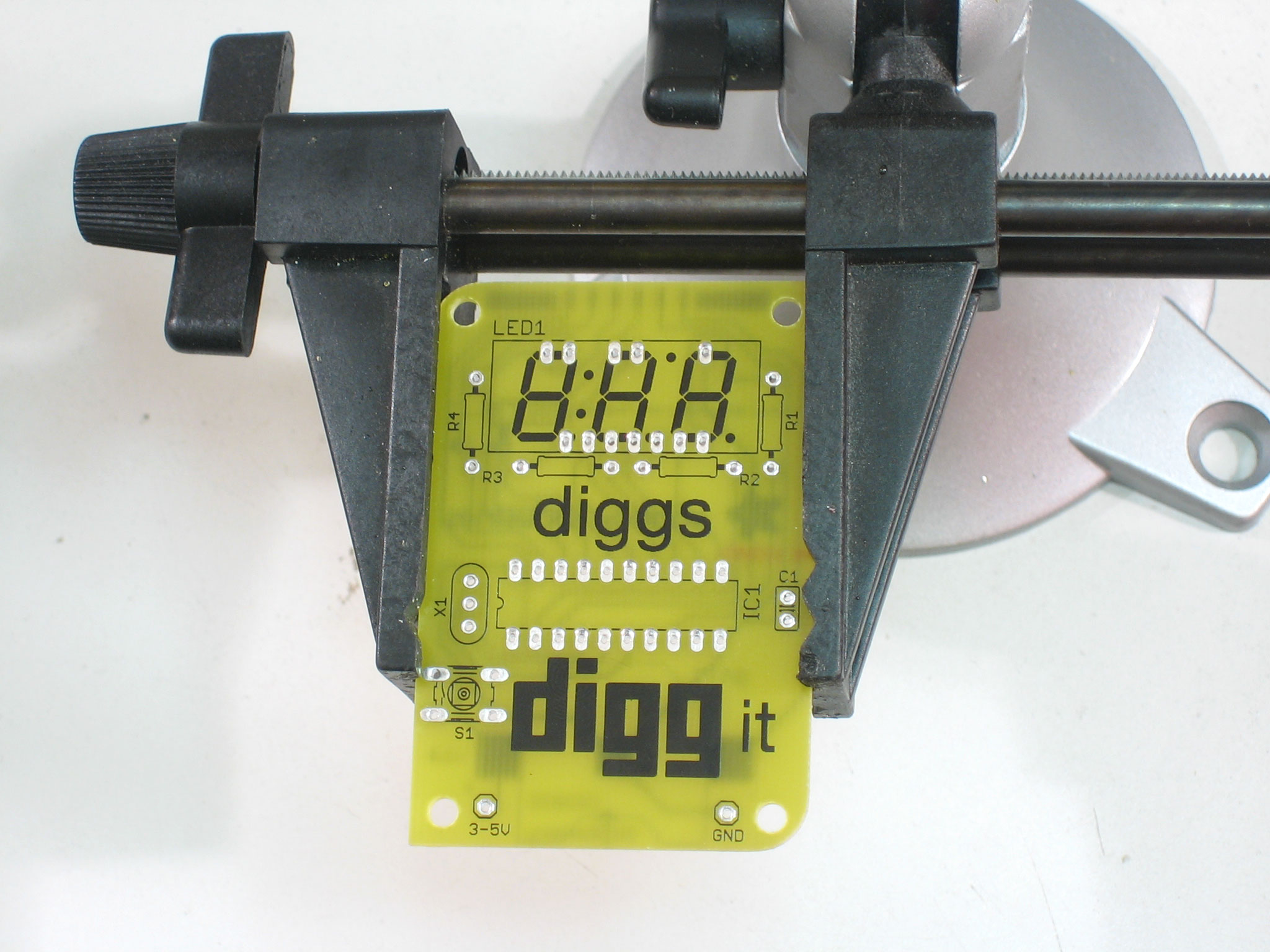 |
Put the circuit board in the vice, ready for soldering! |
 |
Insert the button and LED display. The LED display can only go in one way. The button is symmetric and can go in either way. The button will snap in. Remember that if you want to use a cover, you'll need to install the long-stem button. You may want to slightly bend some of the LED display's pins once its in place to keep it from falling out when you turn the board over. |
|
With the soldering iron ready, solder each pin of the LED display. You may want to tape or hold it in to make sure it doesn't slip. Don't forget to hold the iron tip against both the PCB pad and the pin and wait a second before applying the solder. |
 |
Next, solder in all 4 legs of the switch. |
 |
Next, clip the leads down a little. This is optional but they may catch on something otherwise. |
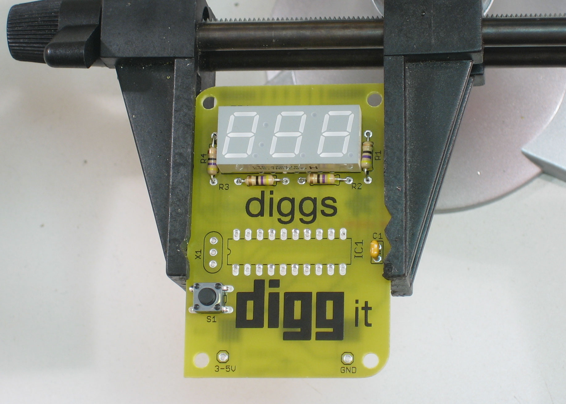 |
Next, place the passive components - 4 resistors and 1 capacitor. The resistors and capacitor don't have polarity: that means you can put them in either way and they work fine. |
 |
When you put the parts with long leads in, bend them out so the parts stay in when the board is flipped over. |
|
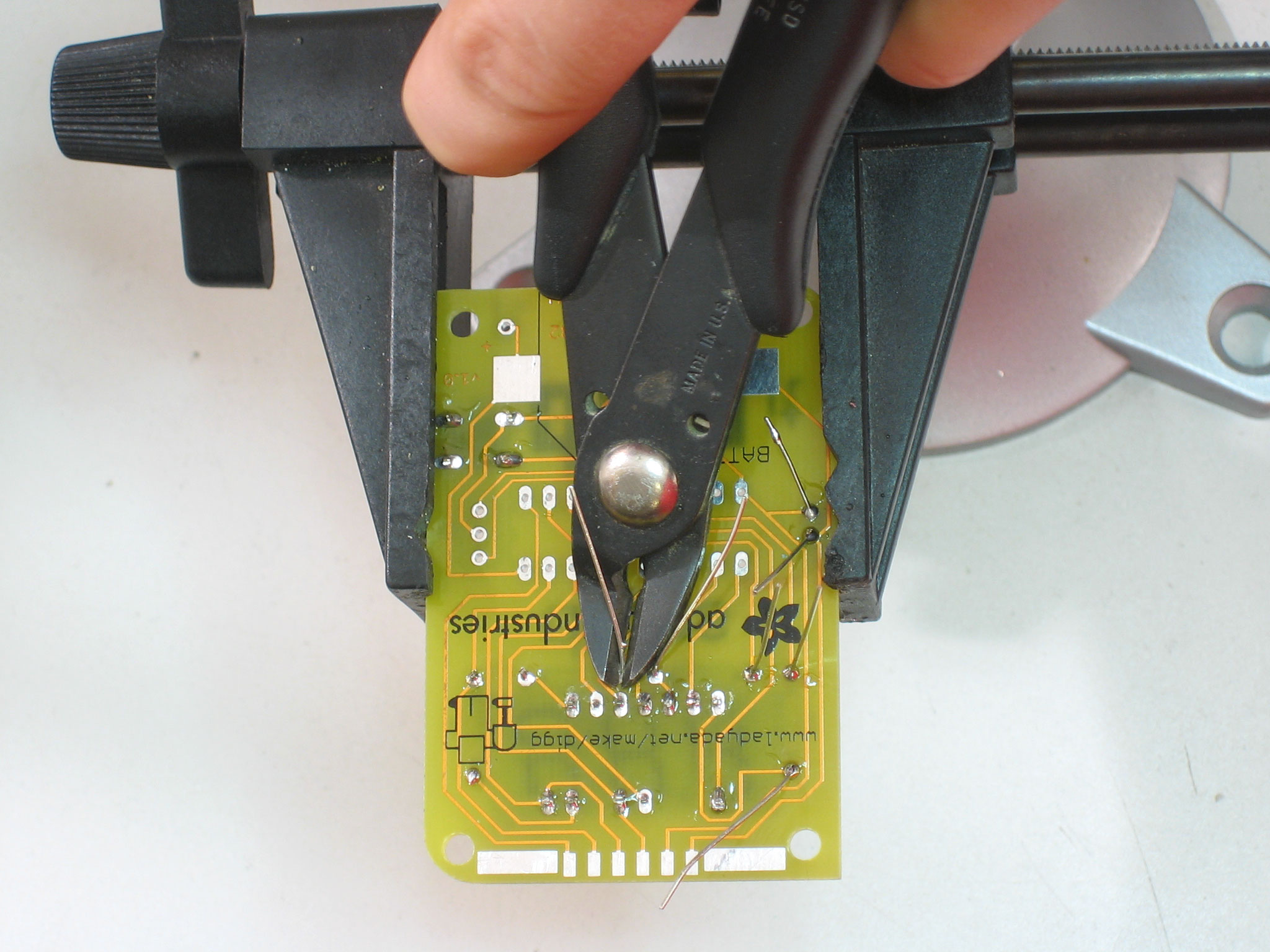
Solder in the passive components and then clip off the long leads. |
 |
Put the microcontroller in. The microcontroller must go in the way shown: there is a small notch on one end of the microcontroller, and this matches the notch in the picture on the circuit board. To get the pins to line up you can try bending them against the table. |
|
Next solder in the microcontroller (after double checking it one last time!). The pins are very short so you dont have to clip them unless you really want to. |
|
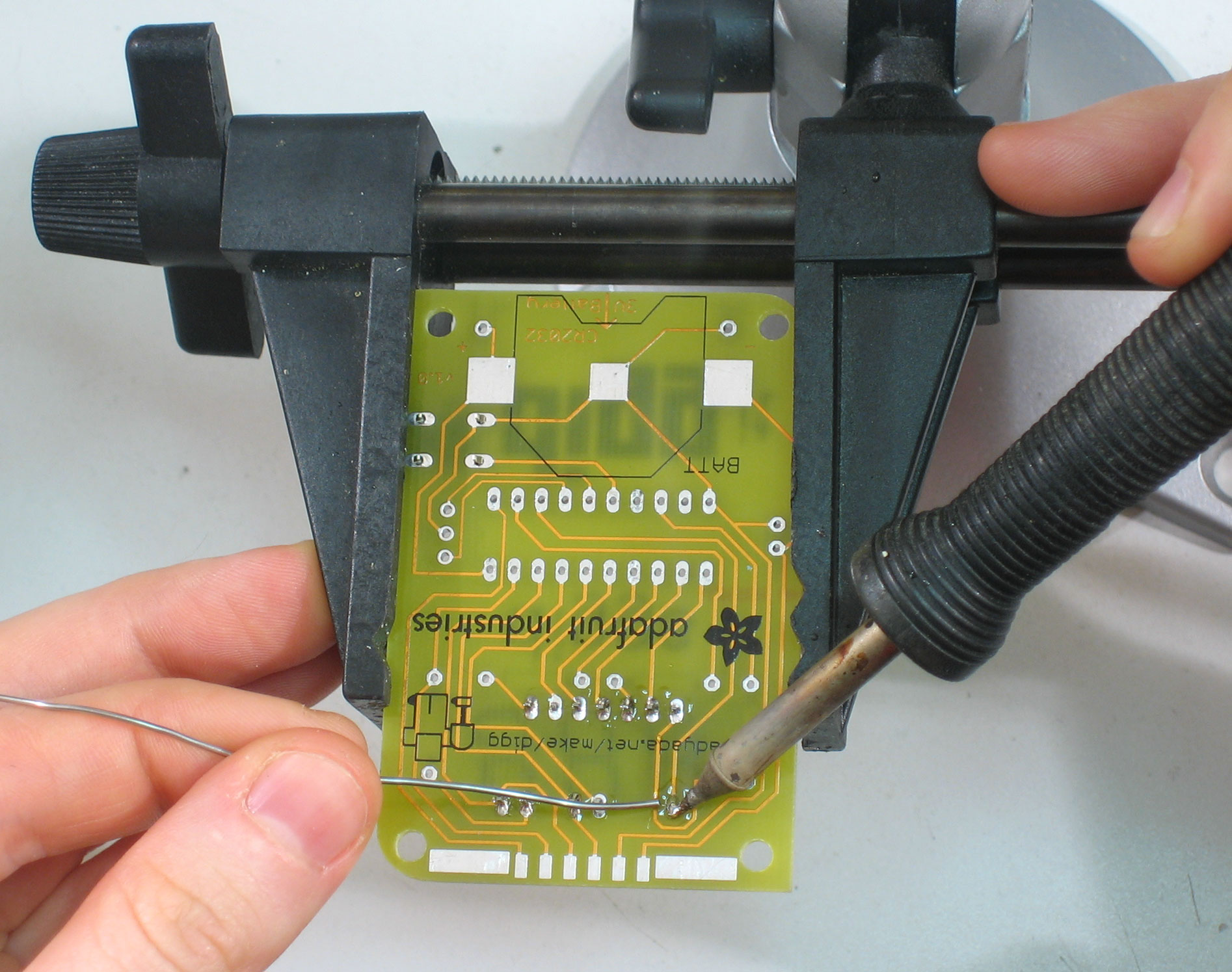
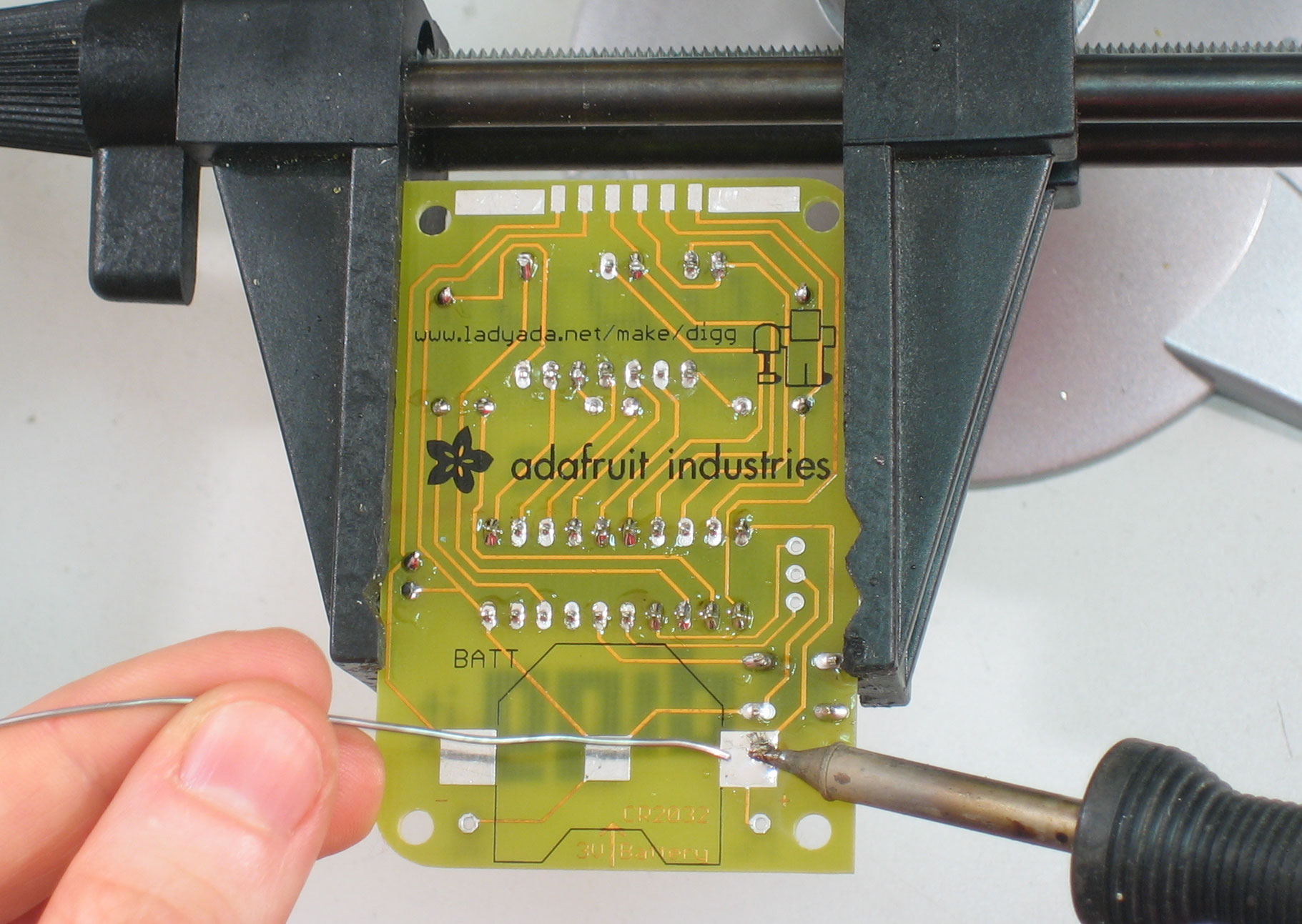
Next is the battery holder. First, melt a small bit of solder onto the middle pad, this will help the battery make contact. (This isn't shown here, but do it anyways!) The holder is a surface mount part (it doesnt have pins that go thru a set of holes). The easiest way to solder this on is to first put a blob of solder on one of the pads. Then, place the battery holder so that it lines up and heat the flange from above so that the solder below it melts. Now that its held in place, solder the other pad. Finally, return to the first pad and just add a little more solder to make sure its really soldered-up well. |
|
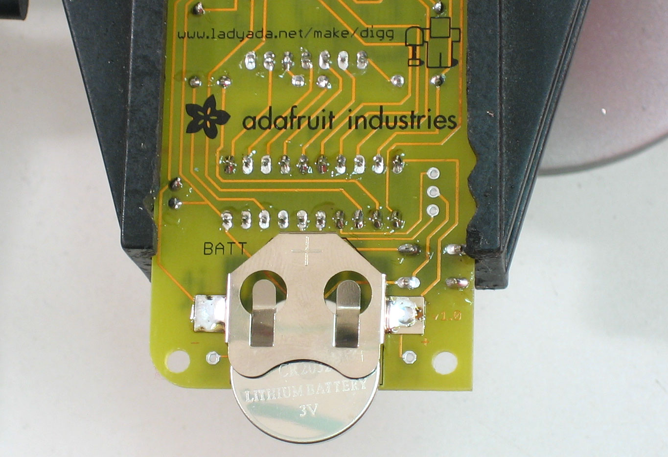
Remove the CR2032 battery from the packaging and slide it in as shown. |
 |
Turn it over, it should display a 0 to indicate its working. Next up, read the user manual! |


Can't get it working? Dont worry, help is available in the forums!