 |
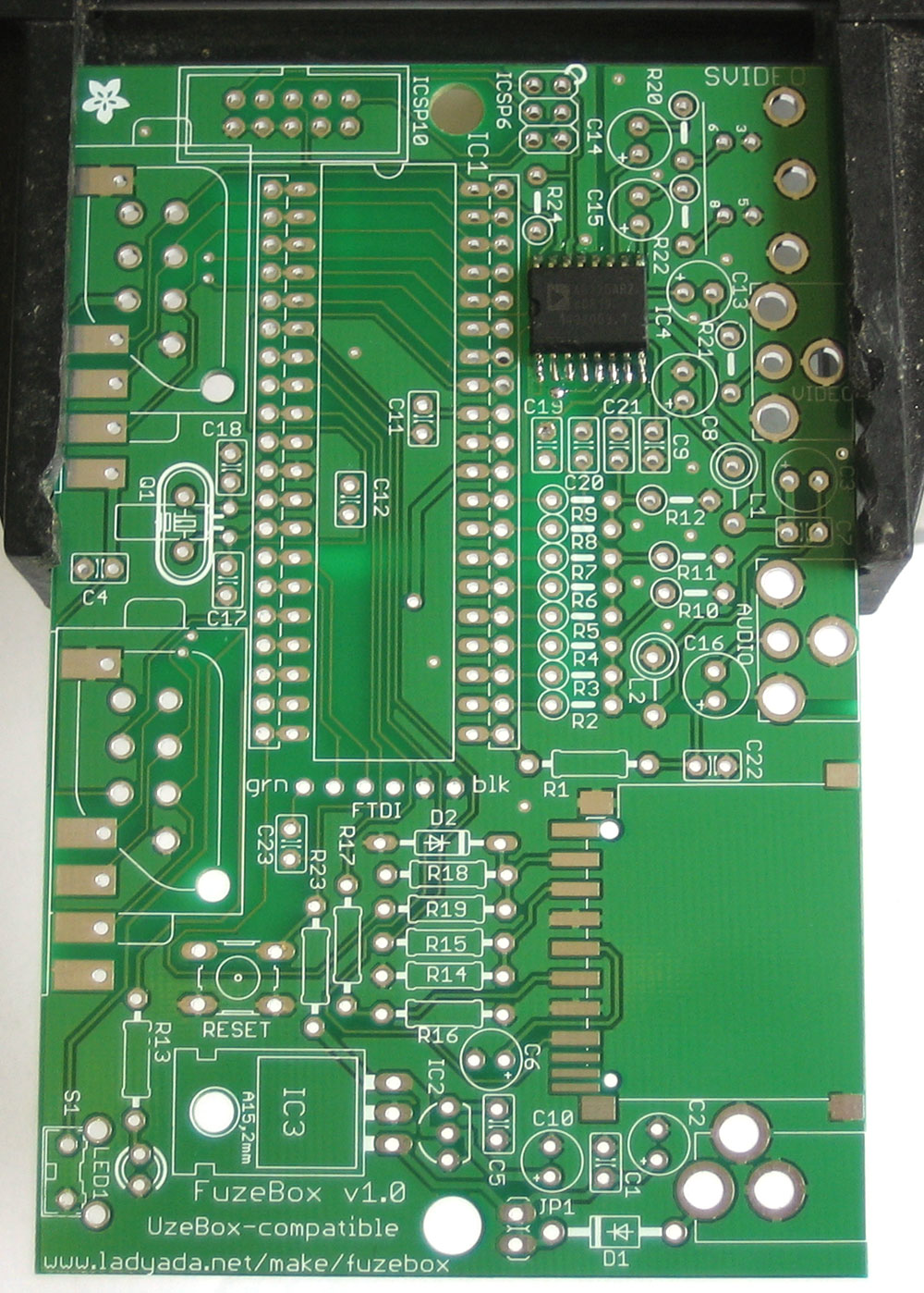
Get ready by checking all your parts against the Bill of Materials (parts list). Once you are sure you have everything, prepare your workspace by heating up the soldering iron, wetting the sponge and arranging your tools and parts so they will be convenient. Get ready by placing the PCB in your vise or holder. The AD725 TV encoder chip should be presoldered if it is purchased as part of a kit. |
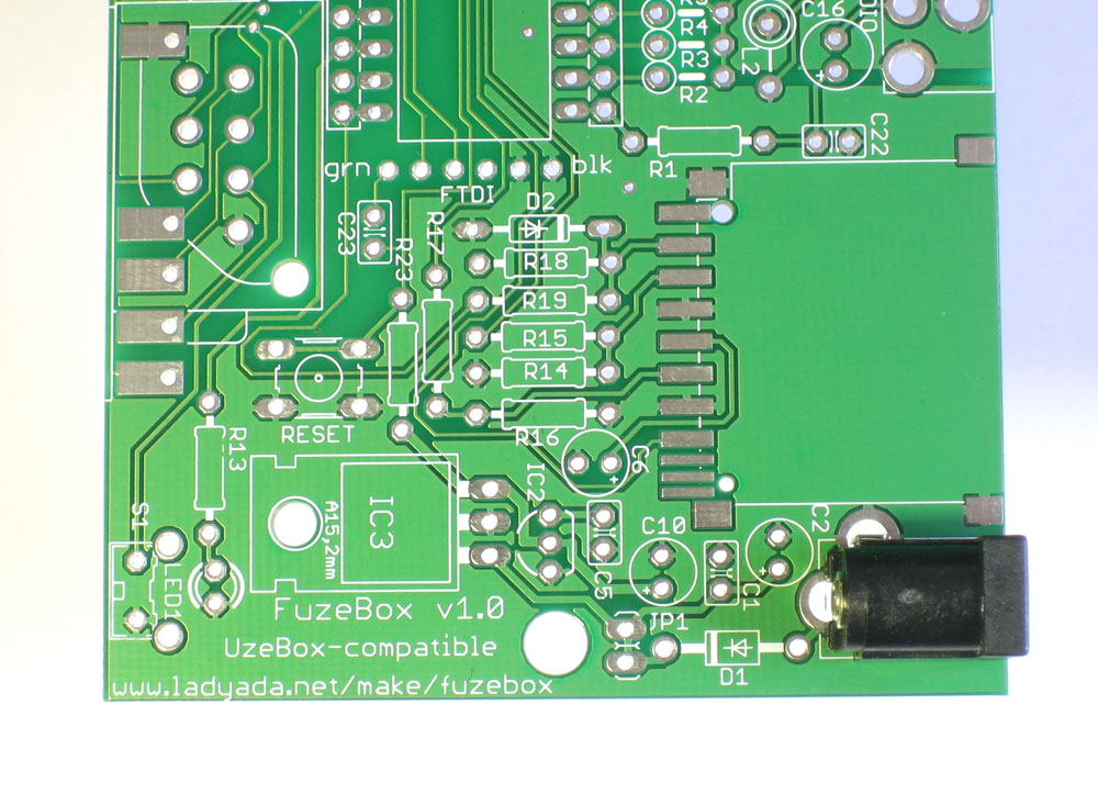 |
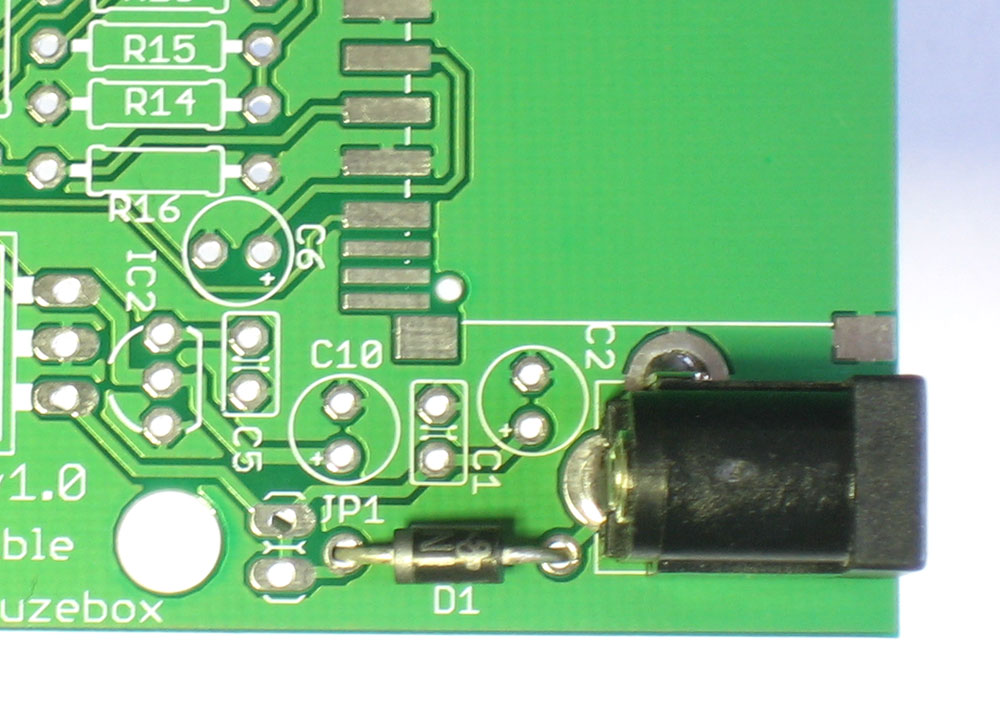
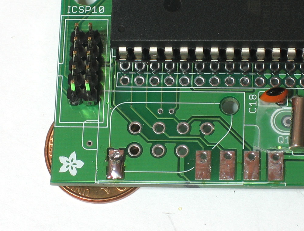
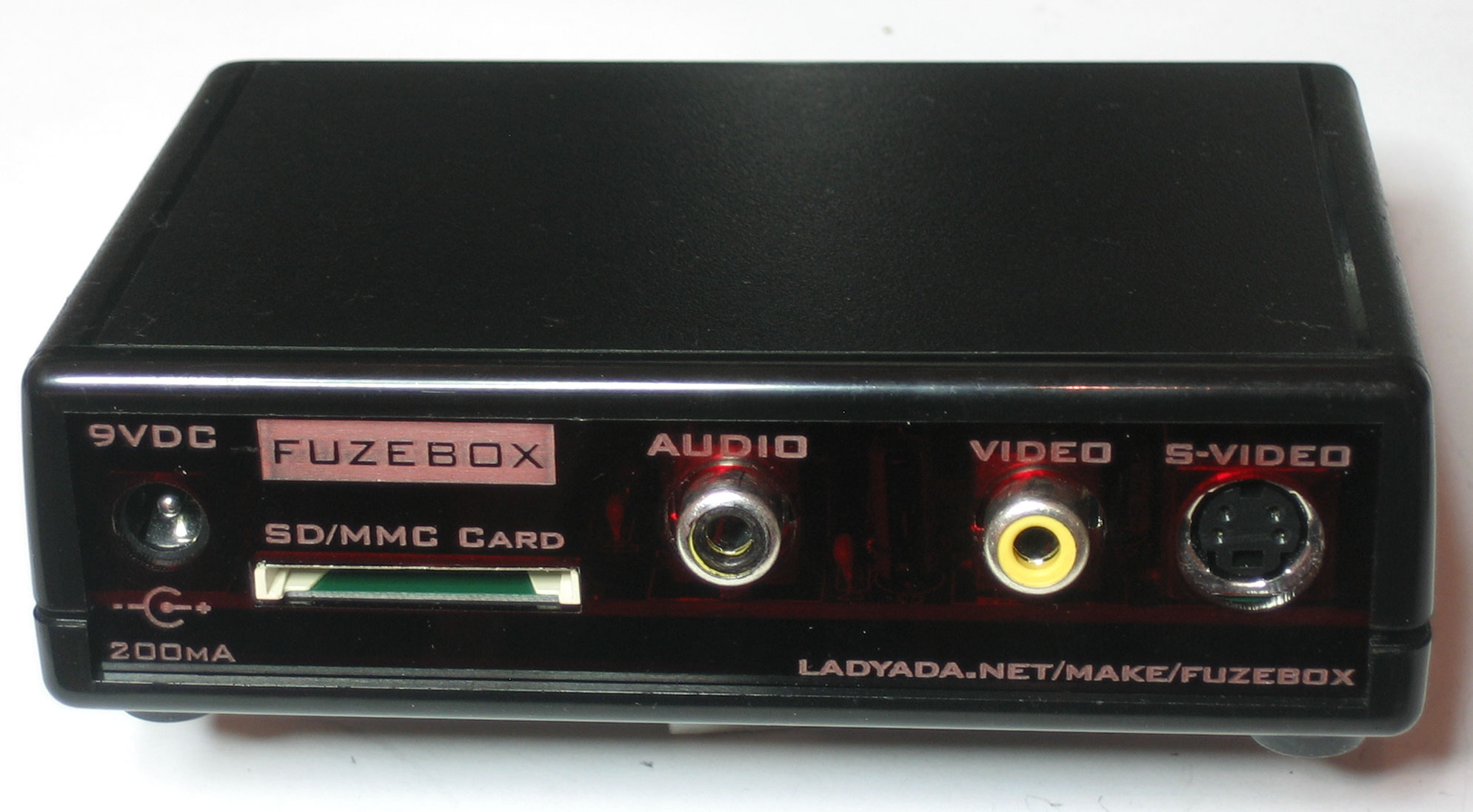
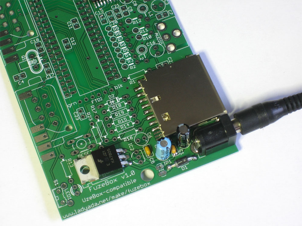
The first part to be placed is the DC jack. This connector allows you to power the Fuzebox using an external power adapter. Place the part as shown, it will only be able to fit in one way. Now flip the board over. If the DC jack doesn't stay in place, you can use a piece of tape to hold it against the PCB, or use a finger if you are dexterous. |
|
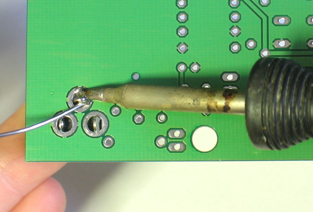
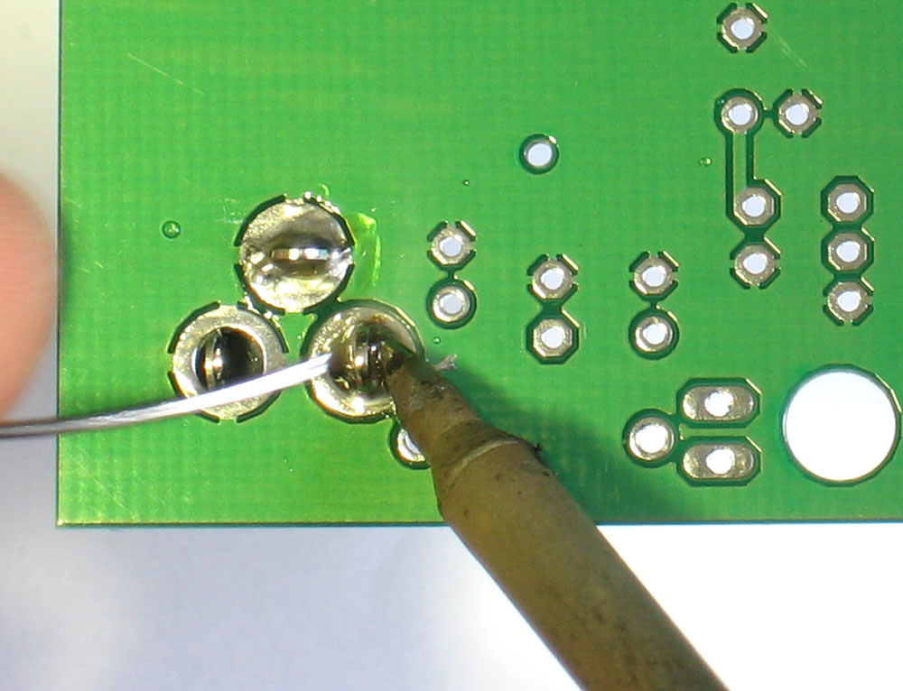
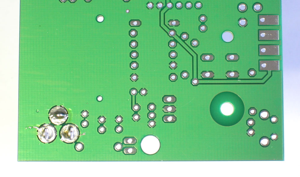
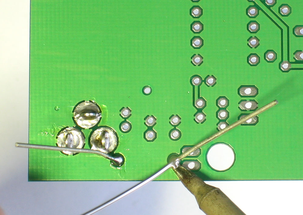
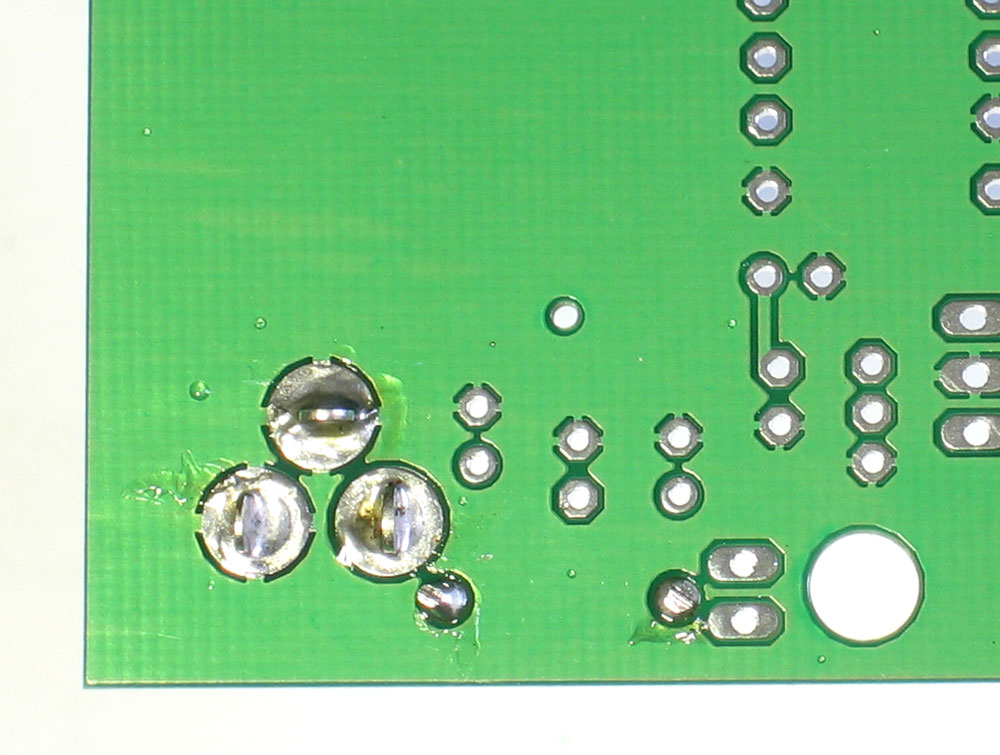
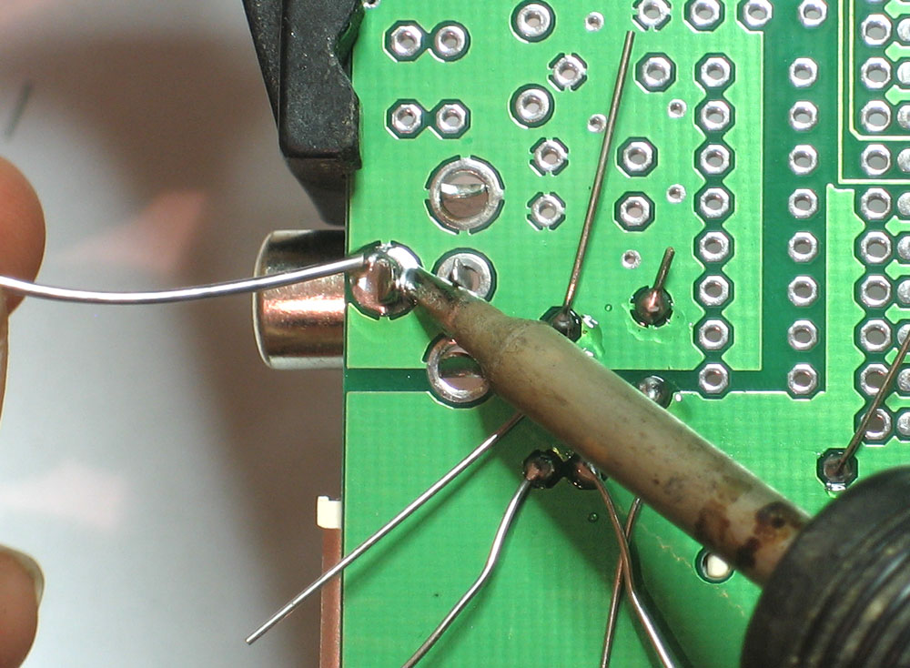
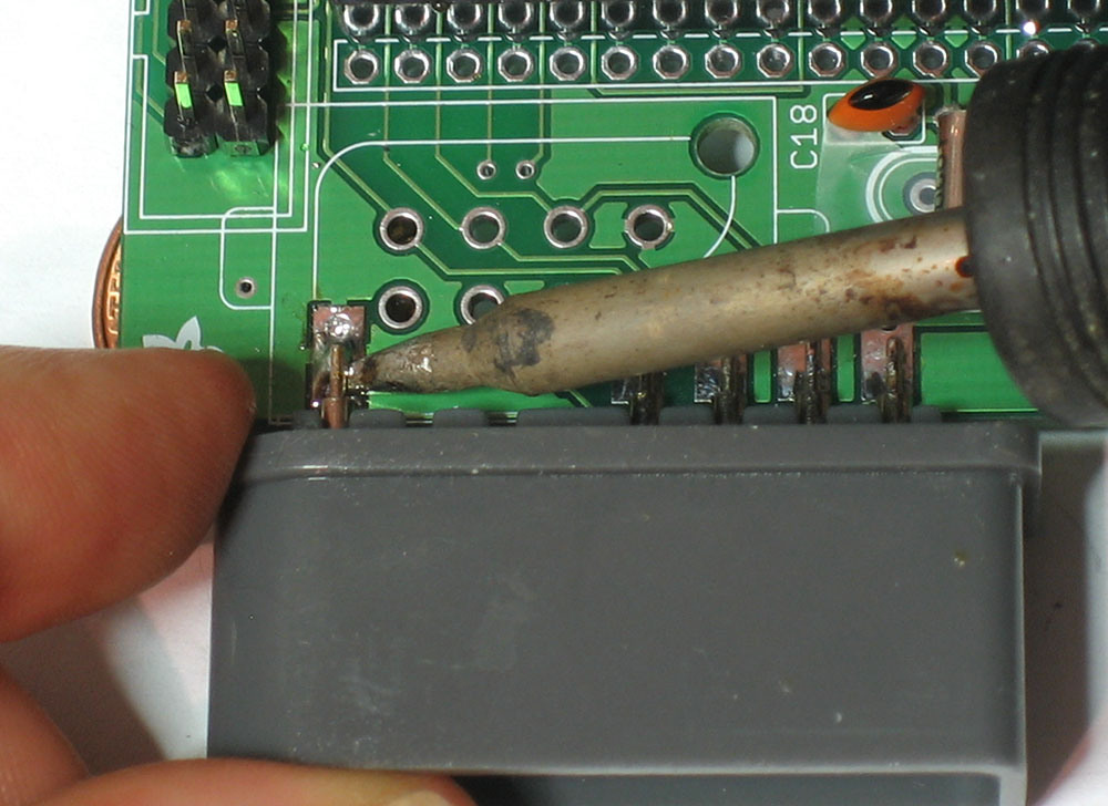
Now using your hot soldering iron, press the long side of the tip against the one of the pins and pads for the DC jack. Wait a few seconds until they are heated up and then press solder into the connection so that it flows into the entire pad. Repeat for all three pads. Make sure there is plenty of solder filling the holes completely, they provide mechanical strength! |
|
Next is the 1N4001 protection diode D1. Diodes are a semiconductor component that only allows current to go one way. By placing a diode between the power input and the circuitry, it helps protect against plugging in a negative DC power supply (backwards) which would make the kit release its 'magic smoke'. As you can imagine, its important to place the component in the right way. On one end of the diode is a white/silver stripe. Make sure this stripe matches the stripe in the silkscreen image. See the image left if you're not certain. Bend the diode into a 'staple' shape and once you've double-checked the polarity, place the diode in the D1 spot. Then bend the leads out a little so that the diode stays flat against the PCB. |
|
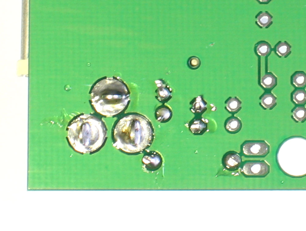
Now using your soldering iron, heat up both the pad and pin of the component and apply solder. Do the same for the other leg. |
|
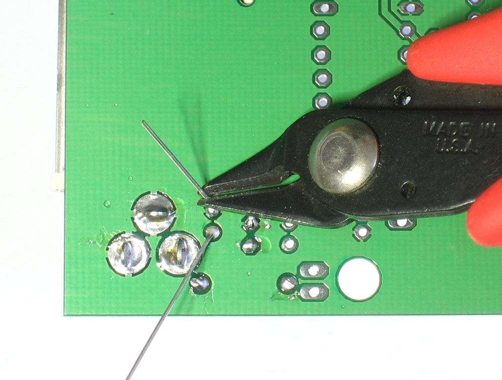
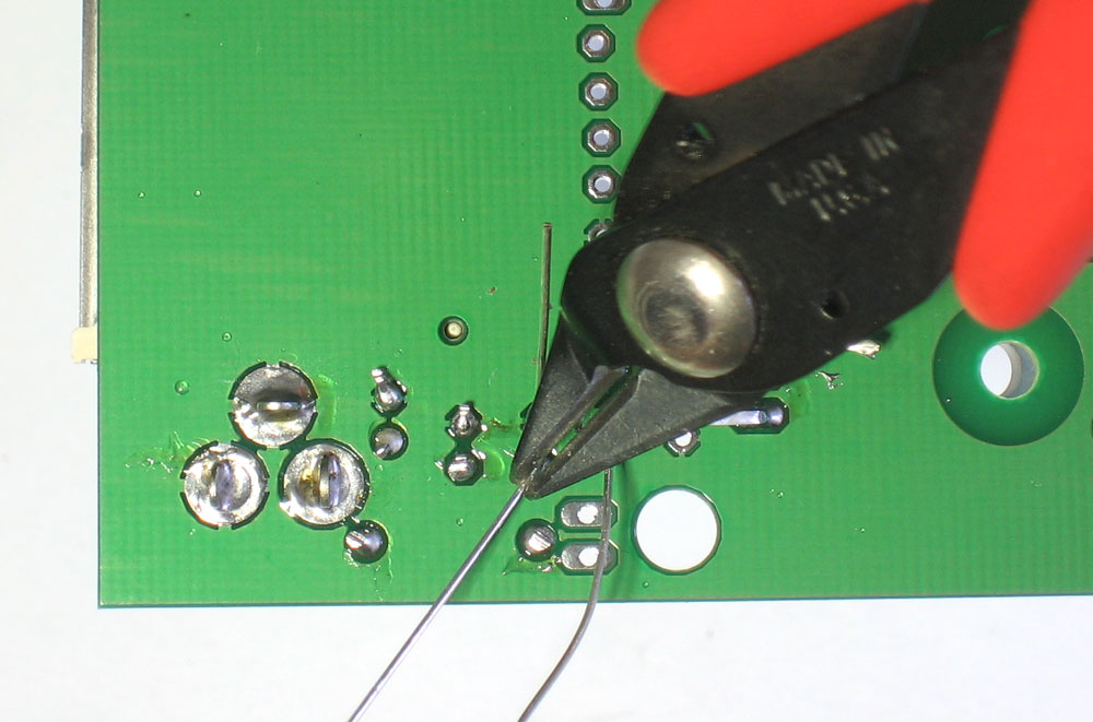
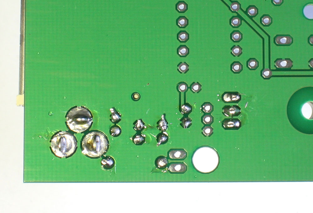
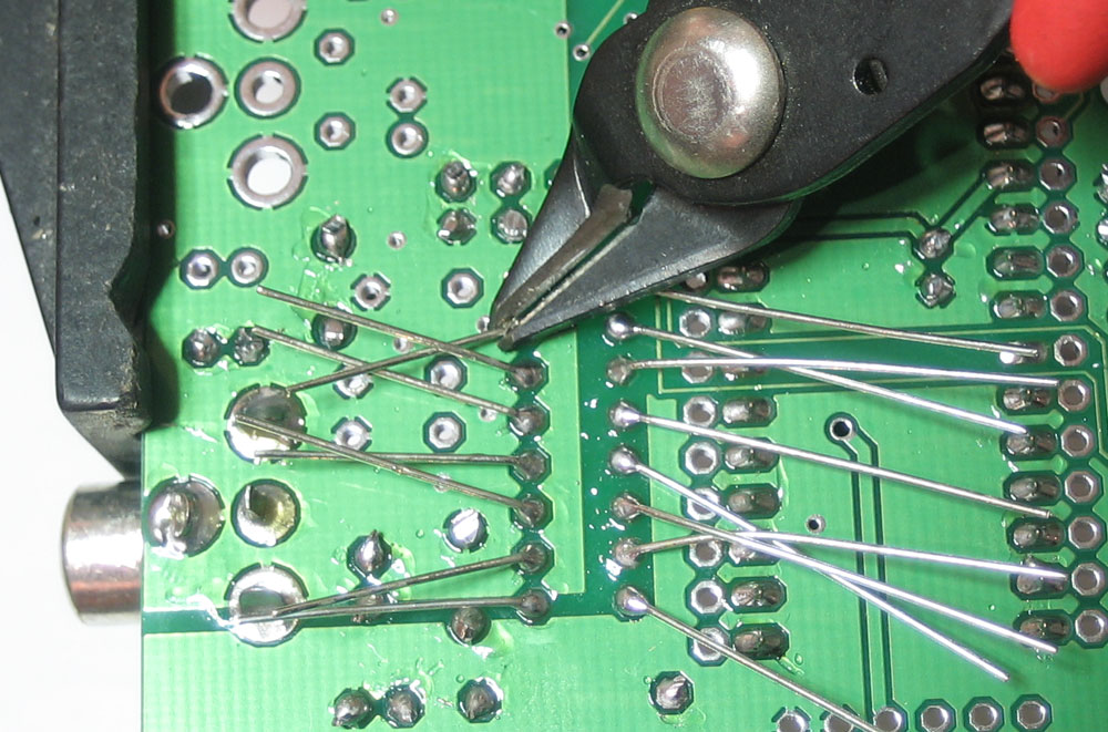
Next it is time to clip the extra long leads of the diode. Using your diagonal/flush cutters, clip the wires right above where the solder joint tapers off.
|
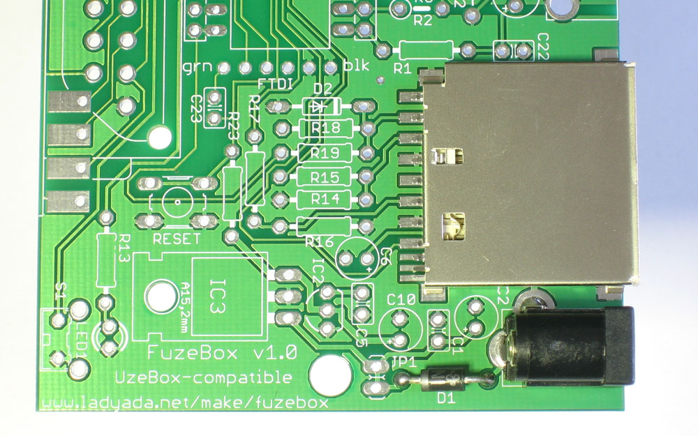 |
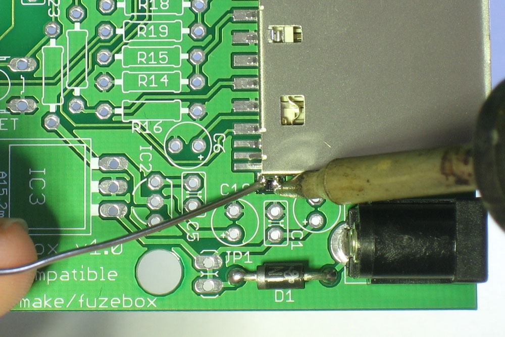
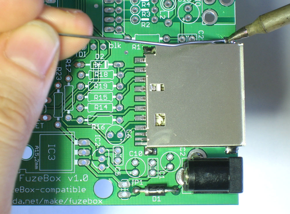
Next is the SD/MMC card holder. This is the connector that holds a memory card for expansion. The SD card holder goes right next to the DC jack and will 'snap' into place so that it sits flat against the PCB. |
|
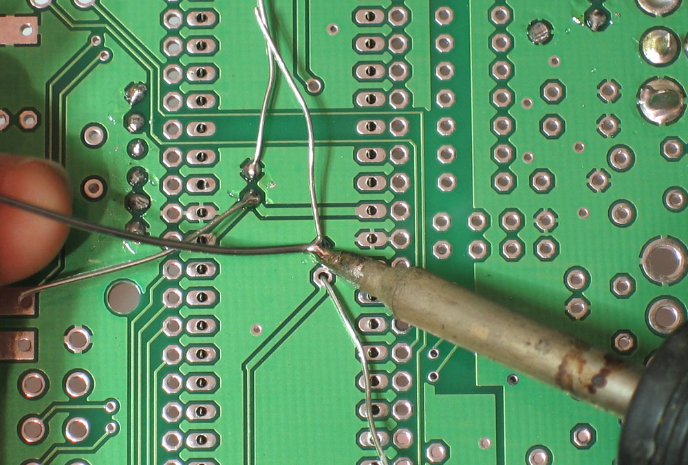
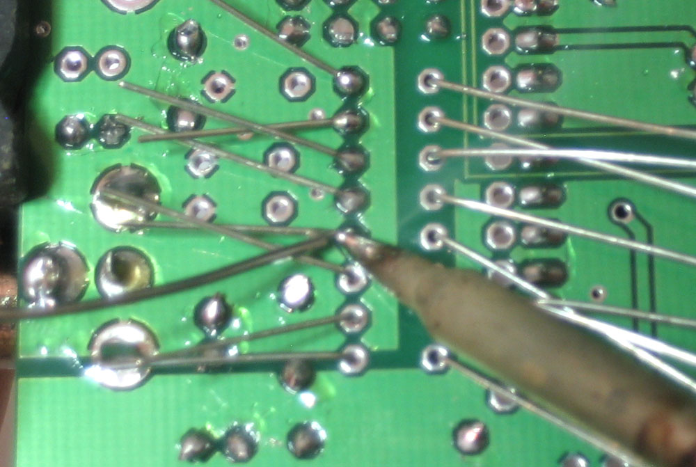
First we will solder in the 4 tabs that hold the card holder securely in place. heat the tab from above and touch some solder in to make a connection. |
|
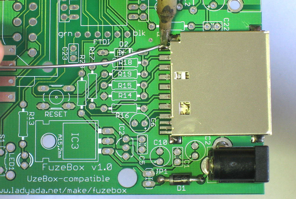
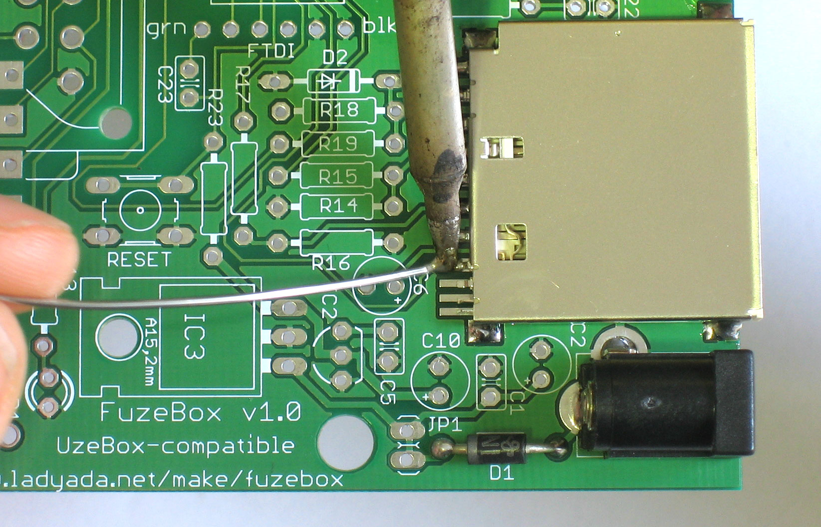
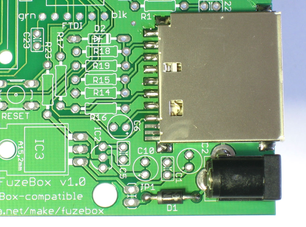
Next we will go through and solder the 8 connections necessary to talk to an SD card. Go through each pin, starting from the top, and solder them to the pad. Be a little more gentle with the holder as the connectors are not as thick as the diode's leads. If you are worried that the SD card looks a little tough, you can wait until you've done more of the kit and feel more experienced. The last three smaller pads don't need to be soldered so just skip them |
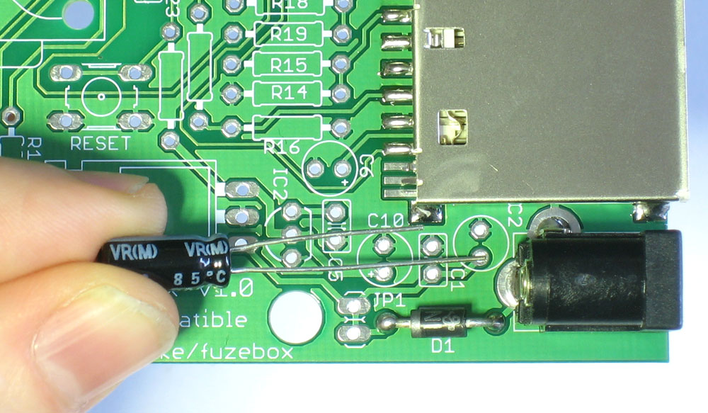 |
Next is C2, the 47uF/25V electrolytic capacitor. This capacitor smooths out any large ripples in power coming into the kit. Electrolytic capacitors are polarized which means they must be placed correctly or they wont work at all. If you look at the capacitor you'll notice one leg is longer than the other, this is the positive (+) lead. Make sure this lead goes into the pad silkscreened with a +. See left for how to place the capacitor. |
 |
Now place C1, a 0.1uF ceramic capacitor. This capacitor is smaller and works with C2, smoothing out smaller high frequency noise. Ceramic capacitors are not polarized so you can put it in either way. |
|
Flip the board over and solder in both capacitors. |
|
Then clip the leads short |
|
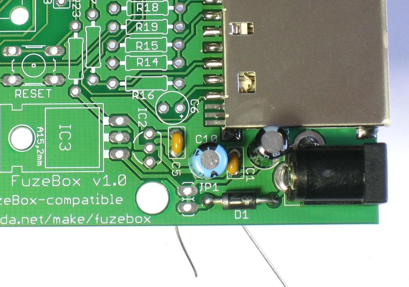
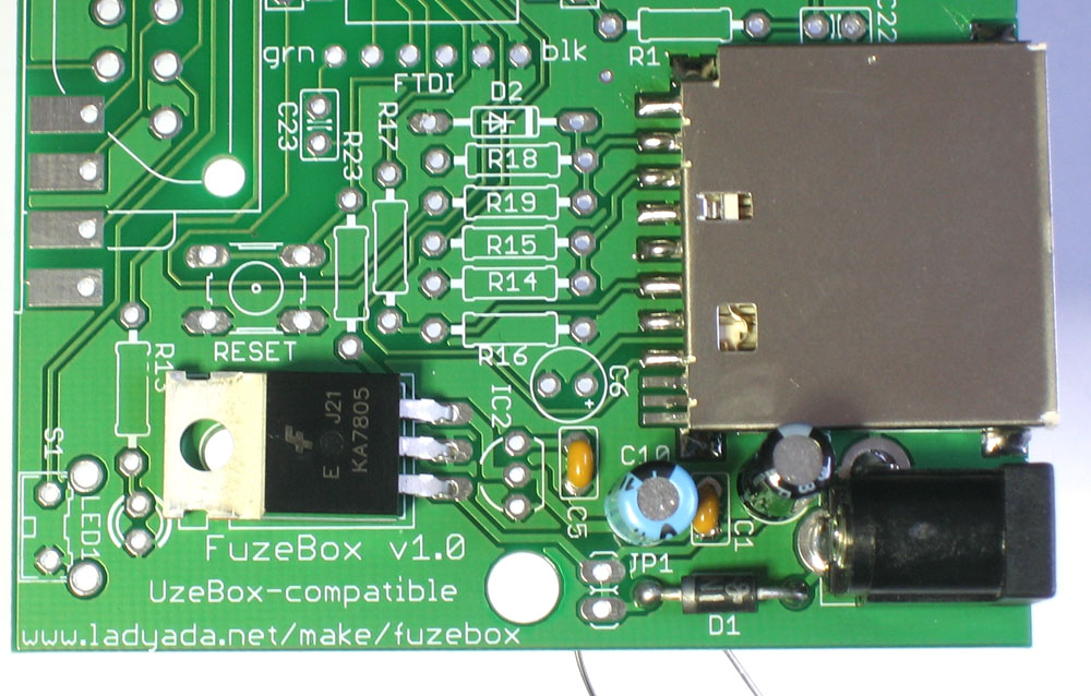
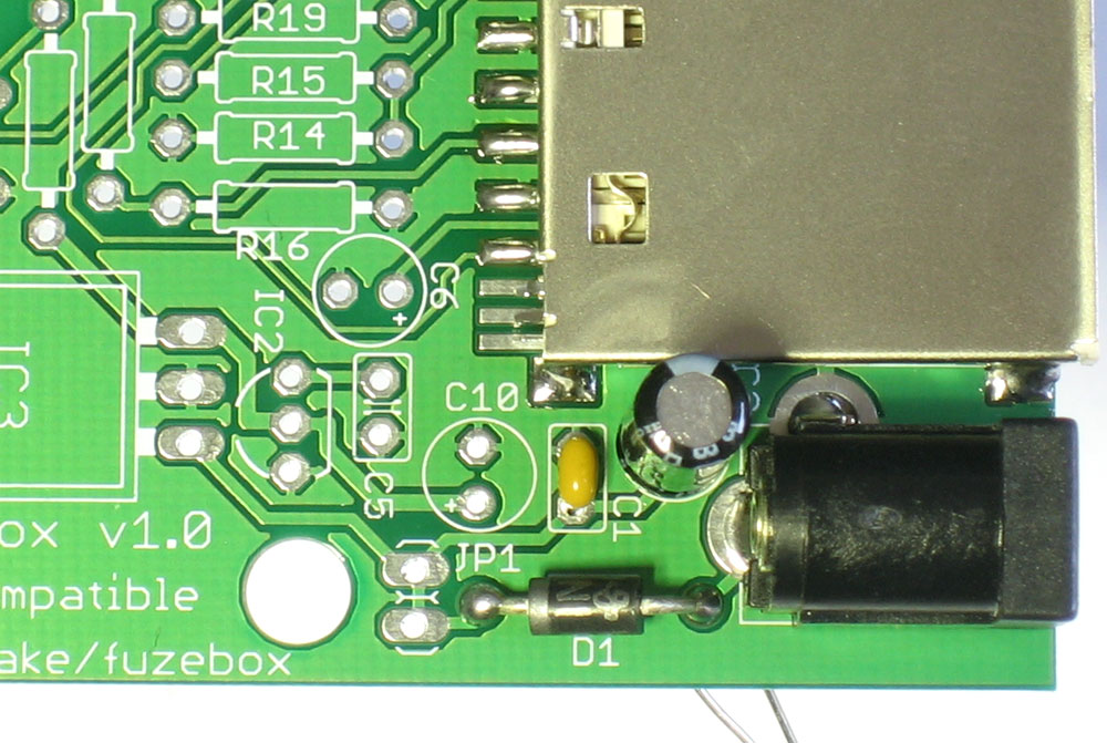
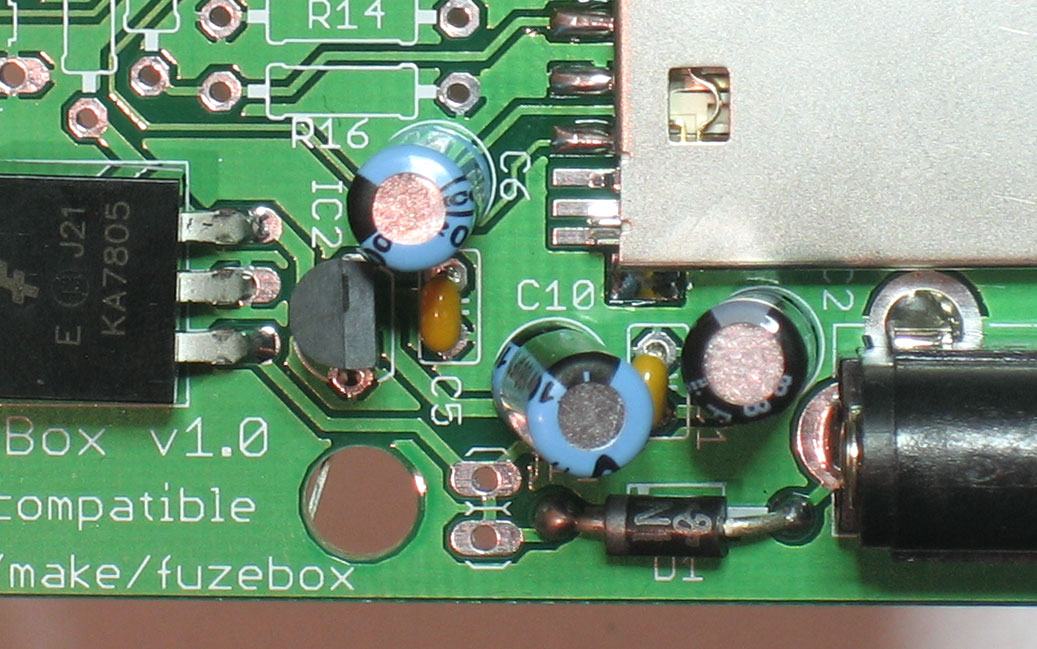
Next is C10, which is the capacitor which helps reduce noise on the regulated 5V supply. It is electrolytic so make sure its placed correctly. Next to it goes the matching ceramic capacitor C5. Finally place the 7805 5V regulator chip IC3. This component takes the voltage from the power adapter, which can be from 7V to 16V, and reduces (regulates) it dow to a nice smooth 5V. Bend the legs into a 90deg angle and then lay the part down so it matches the silkscreen. Don't worry if its not precisely lined up, the silkscreen is just a guideline. |
|
Flip the board over and solder in the regulator and capacitors. |
|
Then clip the leads |
 |
Now is a good time to take a break and test your work so far. Place the board down on a clean surface - make sure there are no stray wires or solder balls, etc. Plug in a DC adapter that provides 7VDC-16VDC and at least 100mA, positive tip. (See this tutorial on how to verify your adapter) |
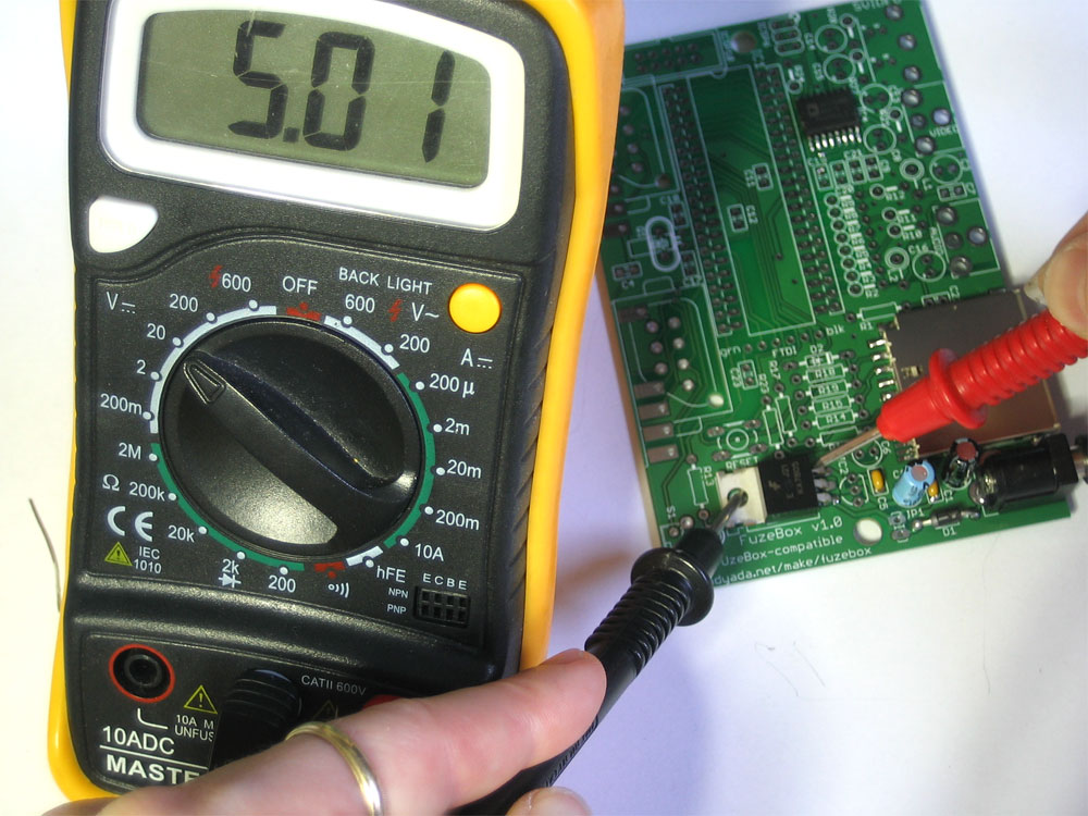 |
Now find your handy multimeter, and set to measure DC voltages (and set the range if necessary). Place the ground/black probe on the big silver tab of the 7805 (which is a ground connection). Then place the tip of the positive/red probe on the third pin of the 7805 (farthest to the right, as shown in the image). You should get a nice steady 5V. If not, check: is the adapter plugged in? is the diode correct? Is the multimeter hooked up right and in the right range? Make sure you have the 5V supply working now, since it is an essential test. |
|
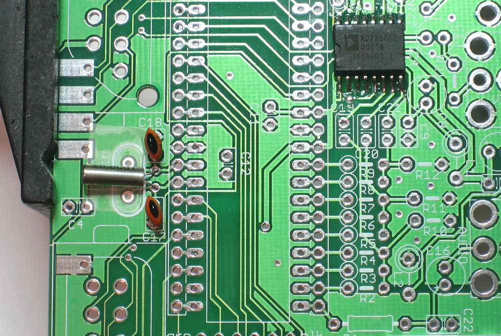
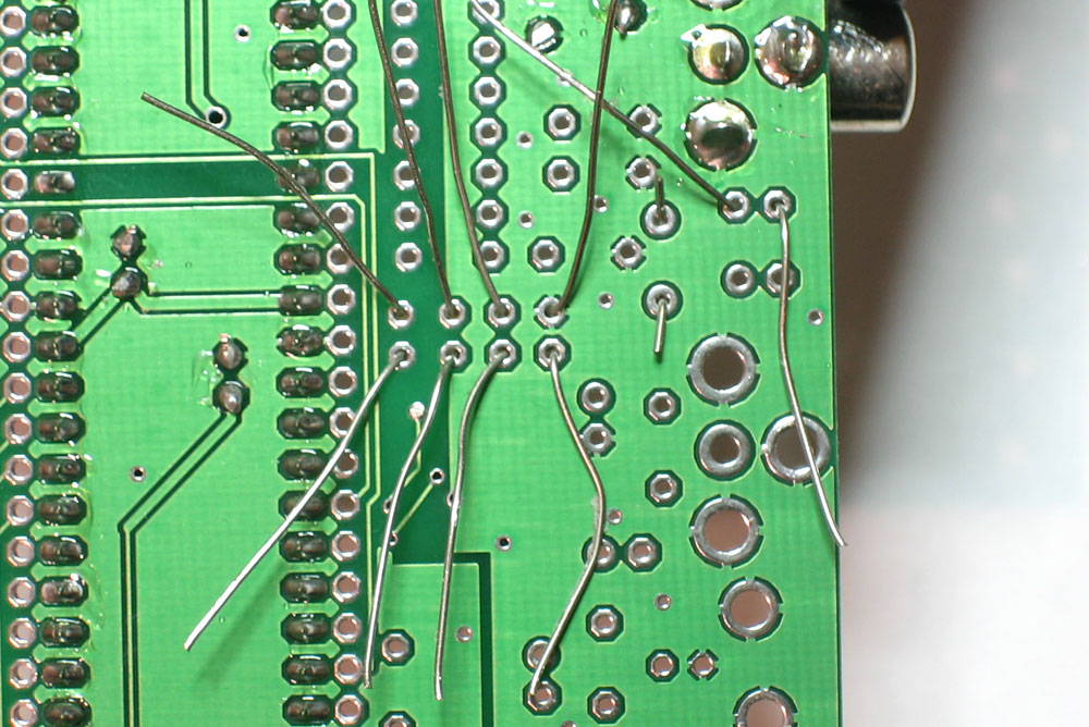
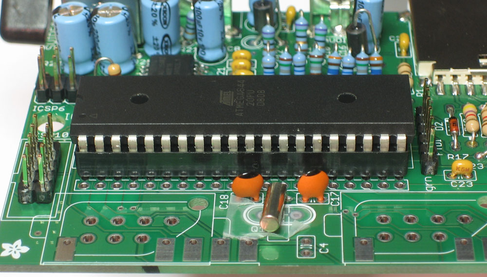
Remove the power supply Next is the 28.63636MHz crystal (which can be cylindrical or tablet shaped) and the two 22pF capacitors. The crystal is what generates the clock signal for the microcontroller. The frequency is chosen because it is a multiplier of the standard NTSC television colorburst frequency, 3.579545 MHz. This allows the microcontroller to create properly-formed/timed signal for a TV. The two small ceramic disc capacitors stabilize the crystal and are essential. Both the crystal and capacitors are non-polar. If you have a cylindrical crystal, place a little tape over the tablet-shaped pads so that when the crystal is soldered in it wont accidentally touch them. |
|
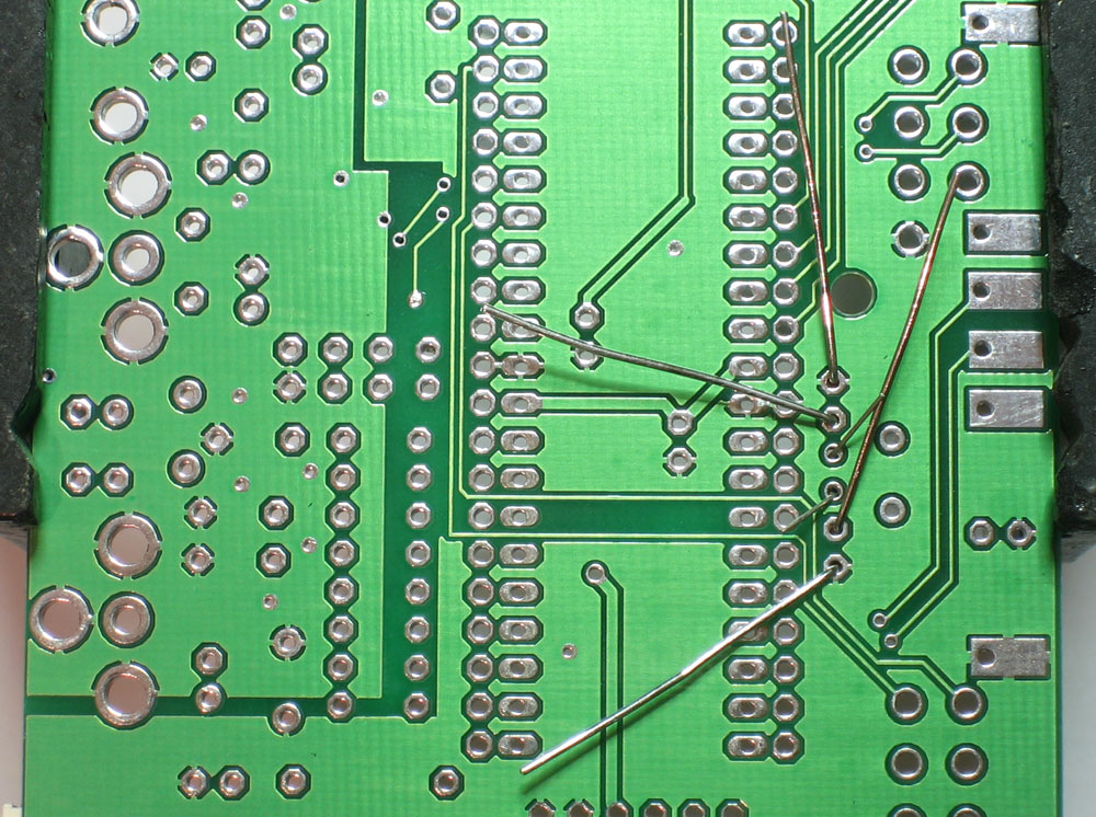
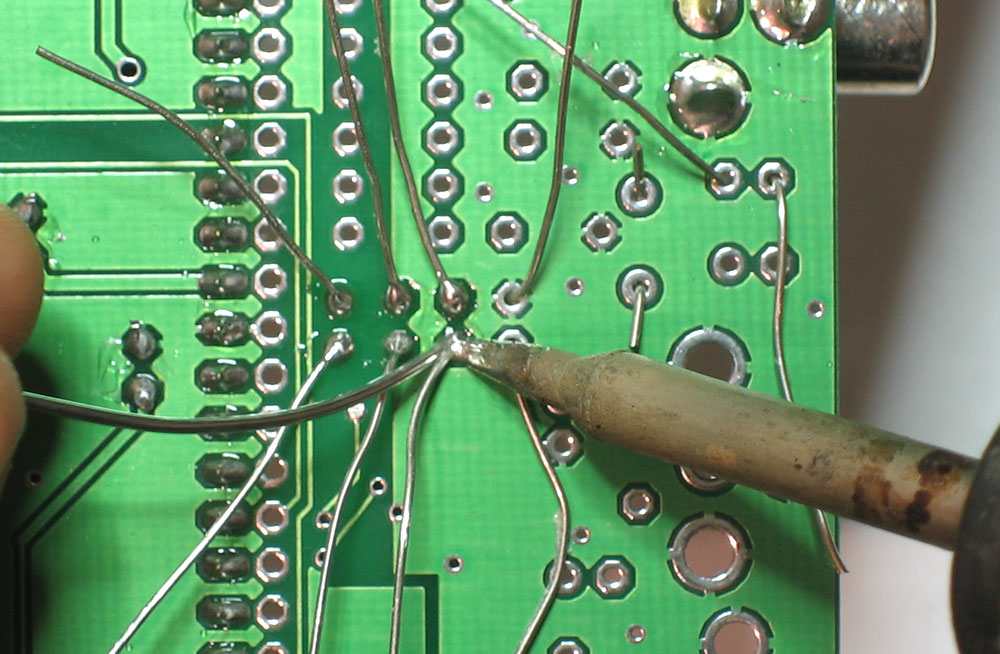
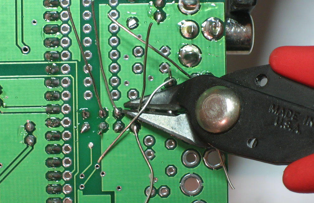
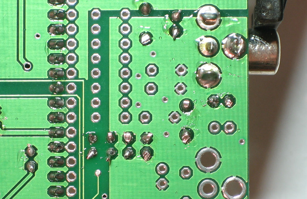
Flip over the board and solder in the crystal and capacitors. Then clip the leads |
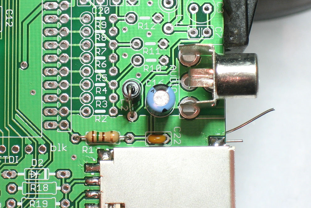 |
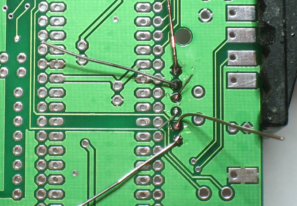
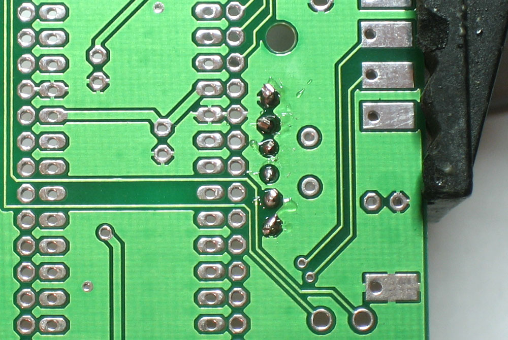
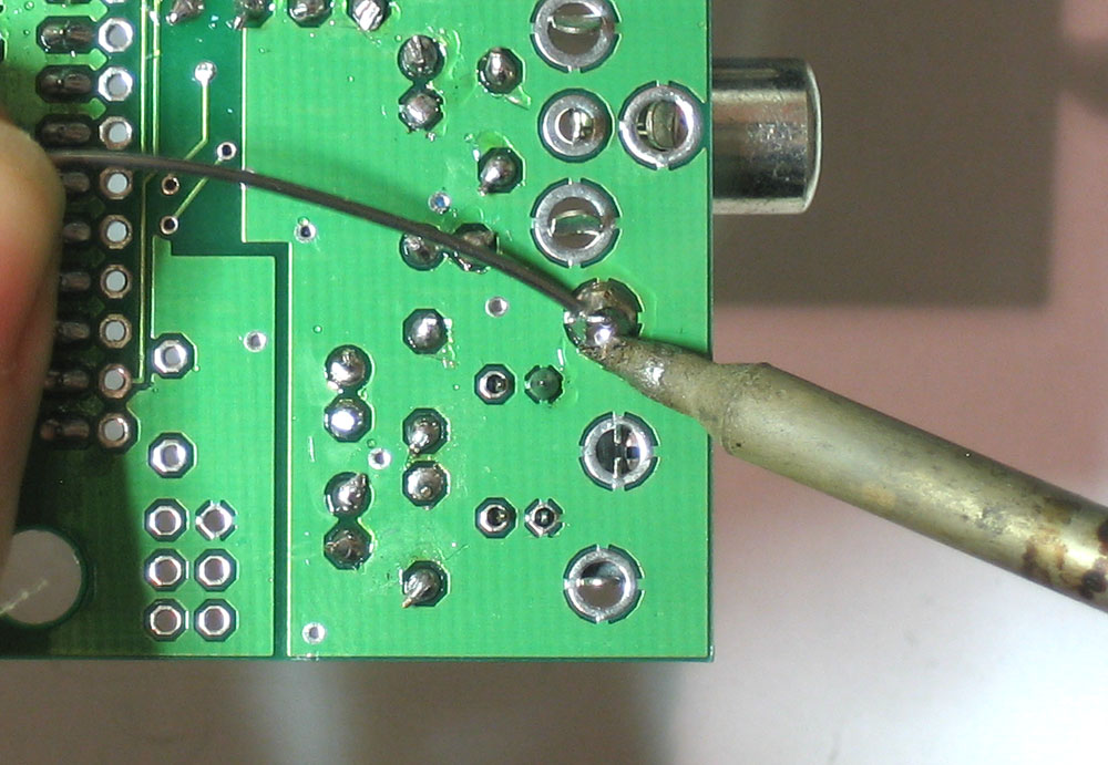
Next is the audio subsystem. The audio that is generated by the microcontroller is generated by Pulse Width Modulation (PWM) - that means that the microcontroller pulses a single pin high and low at very high speed and the long-term average of the pin's output voltage is the sound. We have a small RC (resistor/capacitor) filter that performs the averaging. Place R1 (150 ohm Brown Green Brown Gold) and C22 (0.1uF capacitor) as shown. Resistors are non-polar so don't worry about putting it in backwards. Also place the ferrite bead L2. This provides high-frequency filtering at the power supply level so that the digital noise (of the PWM) doesnt leak into the audio stream through the ground connection. The ferrite bead is also non-polar, but it is bent into a U shape already so try and match up the silkscreen shape. To complete the audio processing circuitry, we will place C16, a 100uF electrolytic capacitor. C16 is a DC-blocking capacitor, which makes sure only AC signal goes out the RCA jack. Finally, place one of the RCA jacks so that it snaps in and sits flat against the PCB |
|
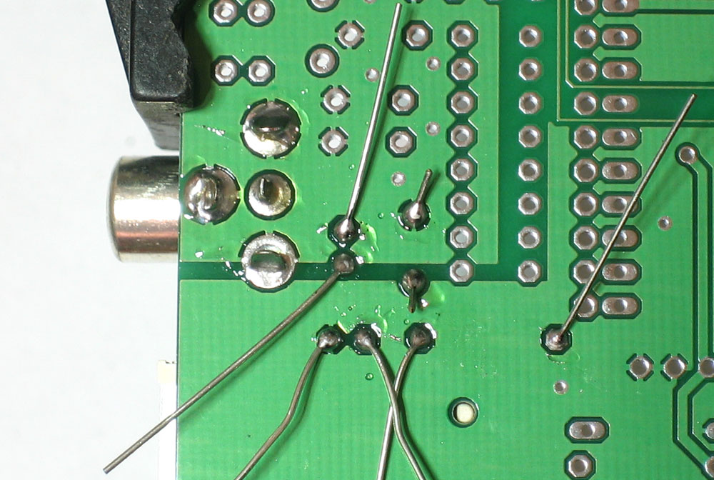
Flip the board over and solder in the 5 components Make sure to put lots of solder on the RCA jack connector as it is a mechanical reinforcement. Finally clip the leads (this isn't shown but you should be good at it by now!) |
|
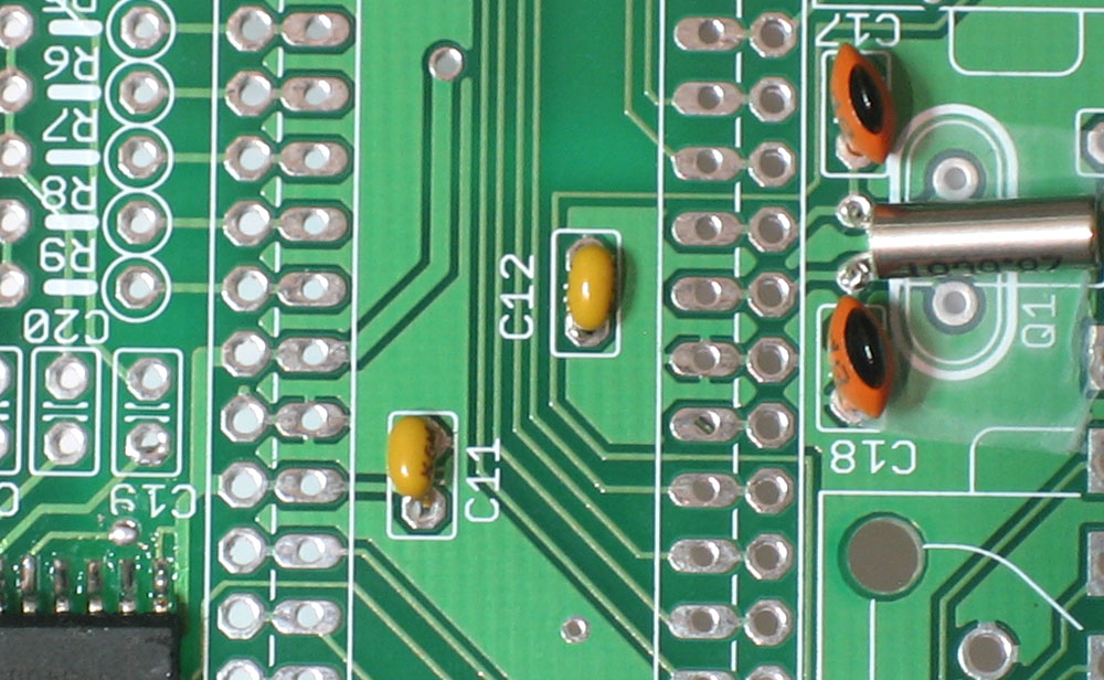
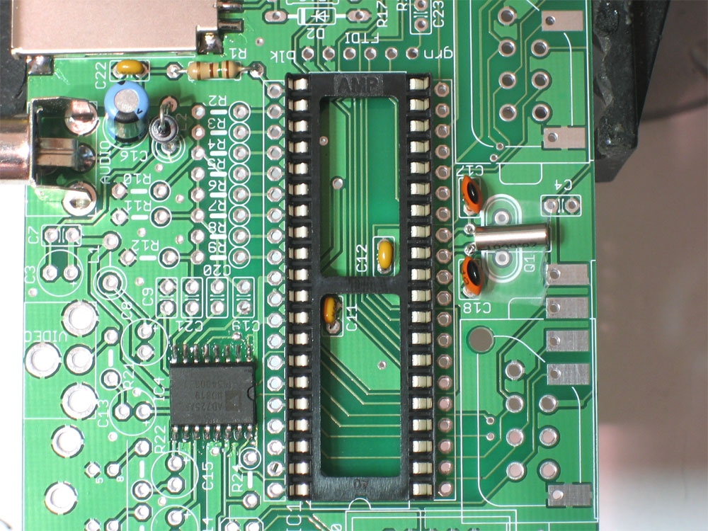
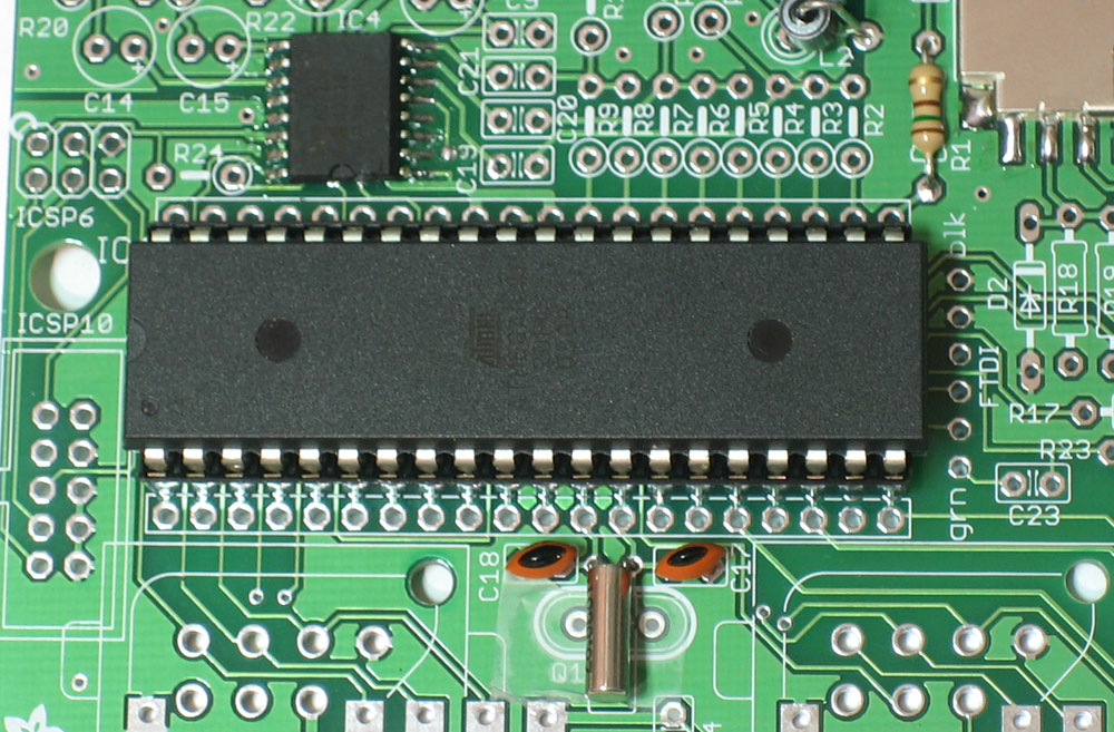
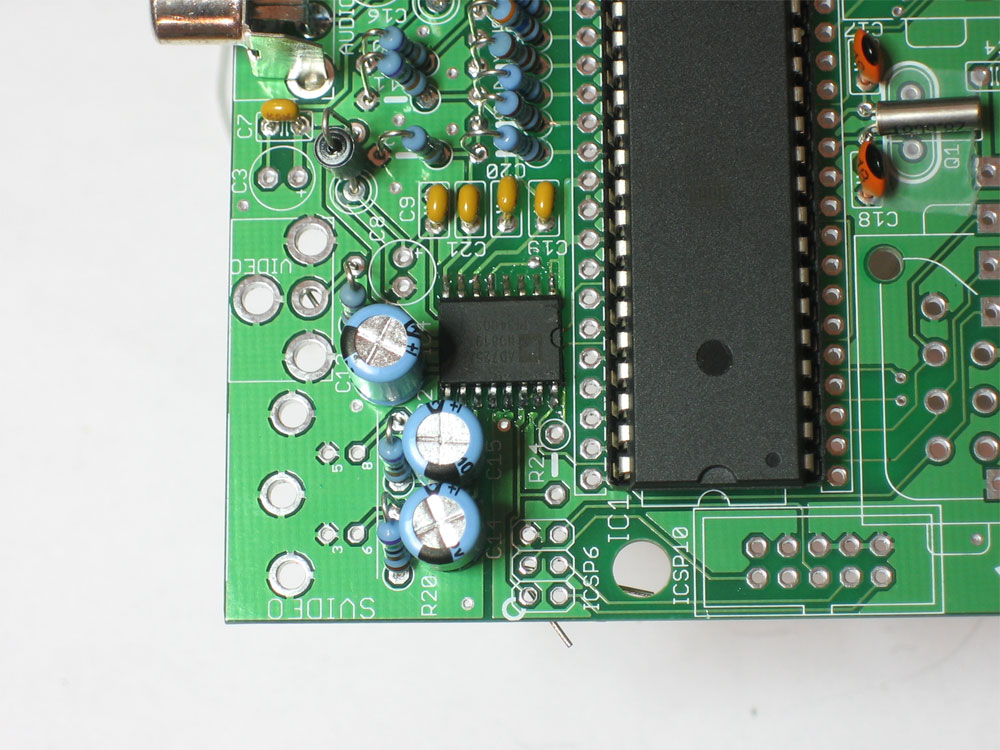
Now it is time to solder in the main processor chip. First, we will place two ceramic capacitors, C11 and C12. These will keep the power going into the microcontroller nice and clean. Next, place the IC socket on top. The socket has a U-shaped notch in one end. Make sure that this notch matches the U-shaped notch in the silkscreen, see the image to the left if you're not sure. If you end up putting the socket in backwards, don't fret. Its not essential that it is in right, but it will help you if you have to replace the chip. |
|
Solder in both capacitors. Then tack two corners of the socket. If the IC socket wont stay in place, use tape to keep it against the PCB. Then go back and re-solder in all of the other pins |
|
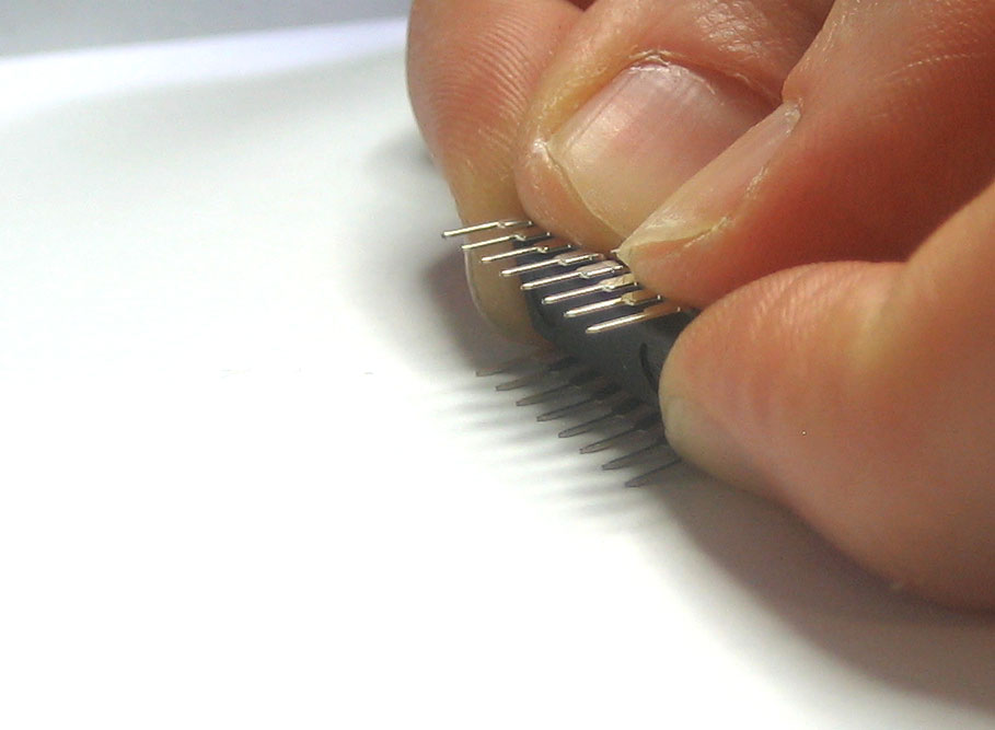
Now it is time to insert the chip! Carefully remove it from the packaging. You'll have to bend the pins in a little to make them fit nicely into the socket. I grab both ends and rock the pins against a tabletop. (The image shows a smaller chip, but the idea is the same). Once the legs are parallel, locate the U-shaped notch in one end. Make sure that this end goes into the notched-end indicated on the silkscreen (and, hopefully, the socket as well) Double check the chip is in right! Now making sure that all the legs are lined up, and not bent or twisted, press the chip into the socket. It should seat itself easily without a lot of force. |
|
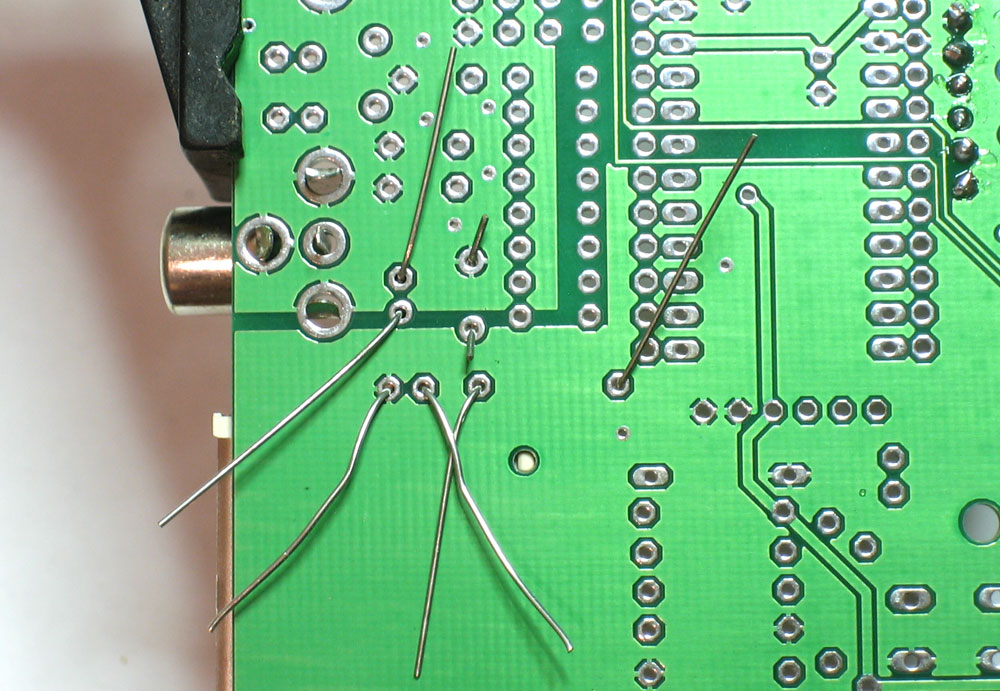
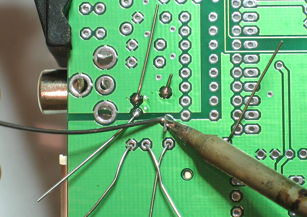
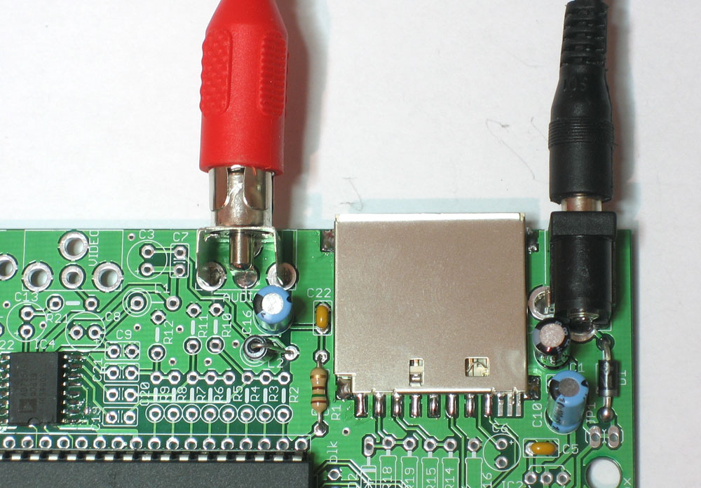
Now its time to test the chip, crystal & audio section. Place the board on a clean table, making sure there's no wire bits or other conductive stuff. Also now is a good time to look over you soldering. Plug in the power adapter and make sure nothing is getting very hot! If you have a device/stereo/tv that will take RCA input, you can simply plug in a cable to the audio output. If you don't, you can use a pair of headphones. Take the jack and press it against the connector so that the large ground ring is touching the outside edge and the tip is pressed against the middle conductor. (See the photo for details) Unplug & replug the fuzebox. About three seconds after it boots you should hear a "kaching" sound indicating it booted OK. If not, make sure the chip is in correctly, and also double check your speaker setup. Remember that you can't connect the fuzebox directly to a large speaker. Hook it up to an amp or use very small earbuds/headphones |
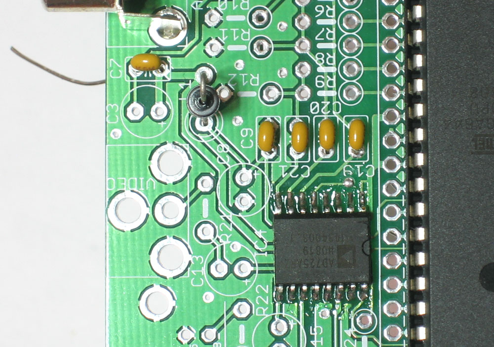 |
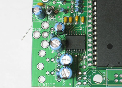
Now that the audio system is tested & working its time to build the video system. Remove the power supply from the board. Place the ceramic capacitors C7 and C9 (used to filter the power supply for the video chip) and C19, C20, and C21 (used to block DC into the video chip). Also place the second ferrite bead L1, which will make sure the video chip power supply doesn't have any digital noise filtering in from the rest of the circuitry. |
|
Solder and clip the parts |
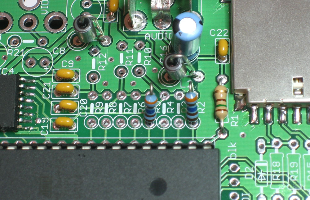 |
Next is the video digital-to-analog-converter (DAC). Basically the video signal is generated by taking an 8-bit port on the chip and using that to create a range of voltages. We can't use PWM to generate the video here because the video is much to fast, at 3.57MHz instead of 20KHz max. To create precise and reproducable colors, the DAC uses 1% resistors instead of 5%. These are blue colored, instead of tan, and have an extra stripe. You may want to pre-seperate the 1% resistors ahead of time since they look very similar and can be confusing. Use a multimeter and/or the parts list if necessary We'll start with R2 and R5, which are 3.16Kohm (Orange Brown Blue Brown Brown). Bend them into U-shapes and place them as shown. Make sure you note that the resistor name is printed to the right of the silkscreen |
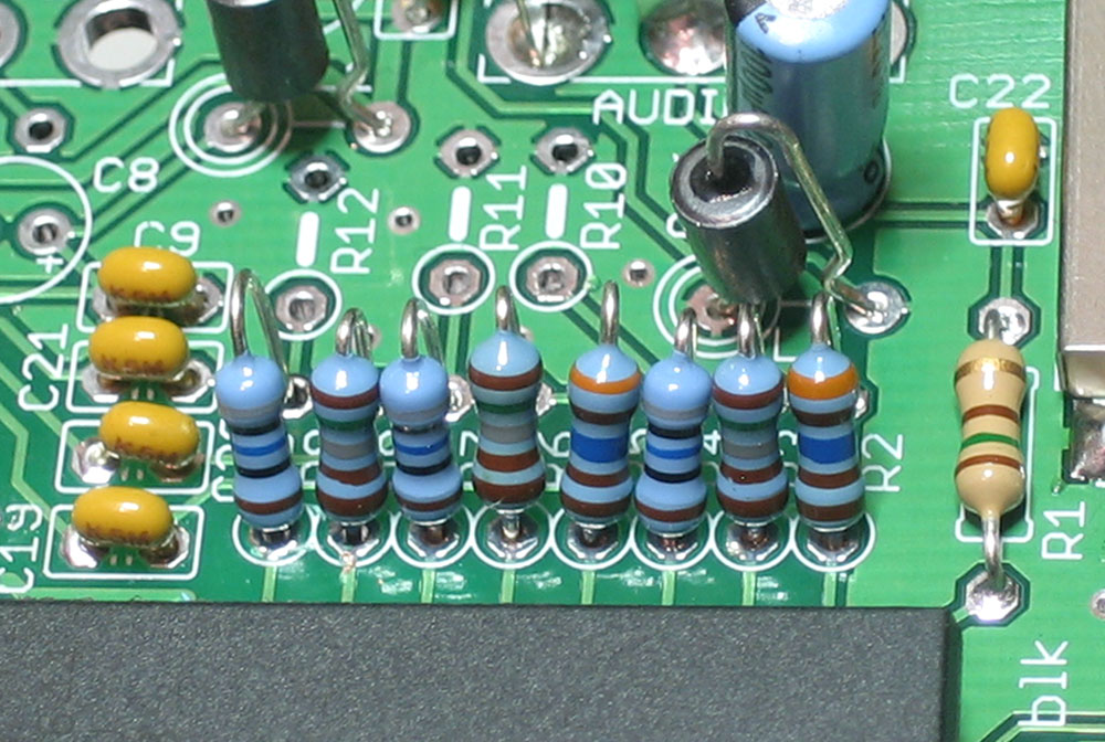 |
Next place the 1.58Kohm (Brown Green Gray Brown Brown) resistors R3, R6, and R8. Then the 806 ohm (Grey Black Blue Black Brown) resistors R4, R7, and R9. Double check your placement against the image to the left. |
|
Solder and clip the DAC resistors. |
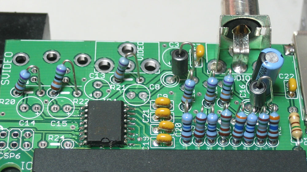 |
Next we will place the six 75 ohm (Violet Green Black Gold Brown) 1% resistors: R10, R11, R12, R20, R21, and R22. These resistors are used for impedence matching. The video chip expects to see 75 ohm resistance on the inputs and outputs, which keeps the signal in the correct range. Solder and clip the resistors. |
 |
Next are the three 220uF capacitors C13 C14 and C15. These are used as the DC blocking caps for the video signal, to make sure the video is AC-only. Remember that electrolytic caps are polarized, so be sure they go in the right way. |
 |
Also, place and solder in two more 100uF capacitors C3 and C8. These are used to stabilize the power supply to the video chip. Remember that electrolytic caps are polarized, so be sure they go in the right way. |
|
Finally, we can place the video connectors, both RCA and S-Video. Snap the connectors in and solder them in. Make sure to use plenty of solder so that they are mechanically strong. |
<screenshot goes here> |
Now that we have the video system up, you can do some real testing! Power up the box with video and audio in to check out your progress! |
 |
Now we will go back and finish the SD card interface we started. SD cards require 3.3V power supply, not 5V so we have a seperate 3.3V supply. Place the 3.3V regulator IC2 first, it is a semicircular IC and it must be placed correctly to work, so verify that the shape matches the silkscreen. Then place the 100uF electrolytic capacitor C6 Solder and clip the parts |
|
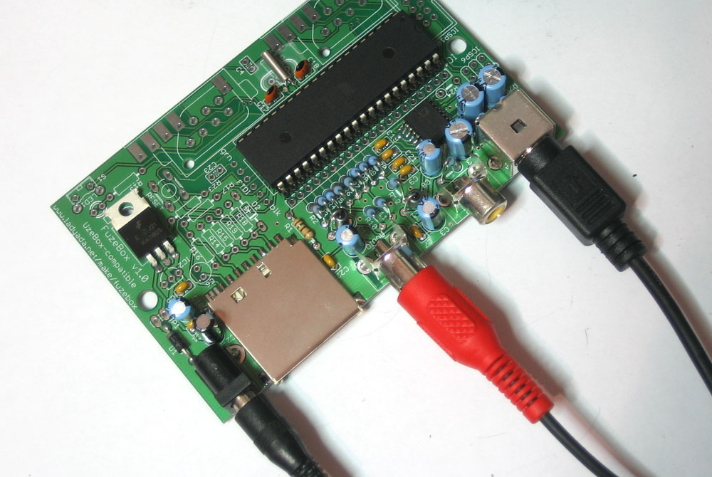
To safely interact with the SD card, we have to convert the 5V data lines from the microcontroller to 3.3V. We will do this with a combination of resistor dividers and a zener diode. Place the zener diode D2 first. Like the 1N4001 diode from the power supply, this diode has a stripe, this time black, that must match up with the silkscreen image. Next place the three 1Kohm (Brown Black Red Gold) resistors R14, R16 and R19. Then place the two 470 ohm (Yellow Violet Brown Gold) resistors R15 and R17 and finally the 4.7Kohm (Yellow Violet Red Gold) resistor R18. Double check the resistors, especially the 470 and 4.7k ones, to make sure you have the right ones in place. Solder and clip the components. |
|
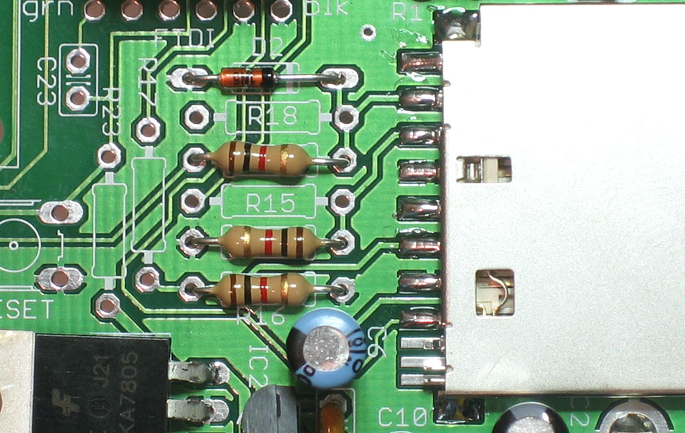
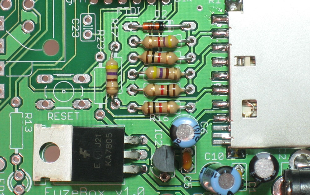
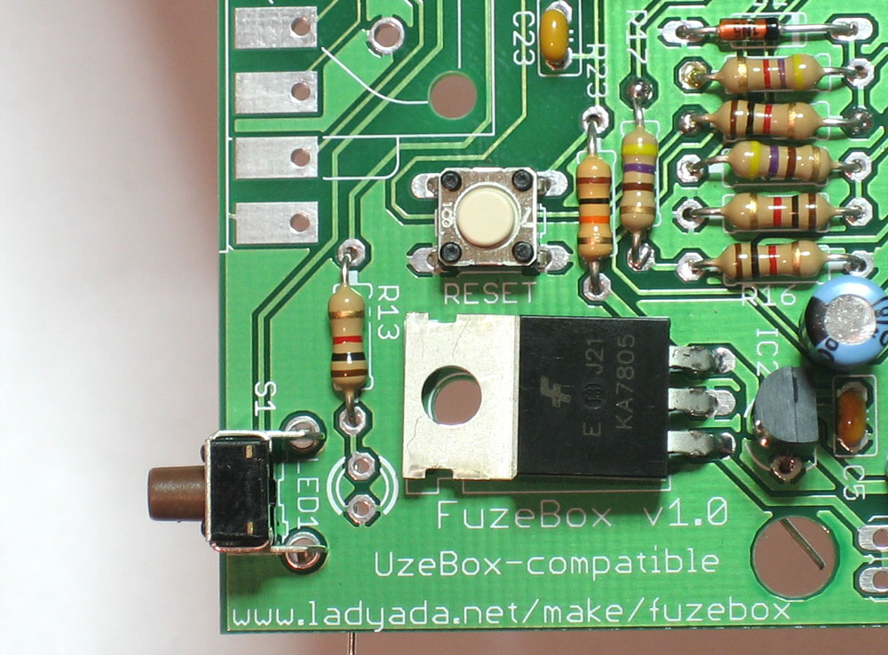
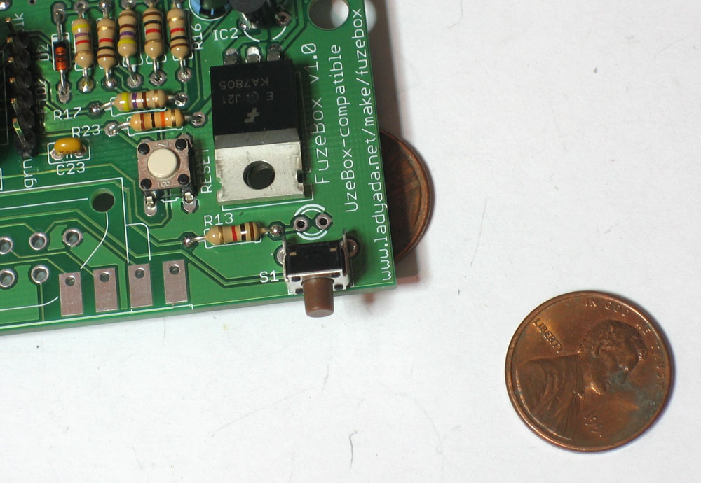
Next up are the two buttons S1 and RESET, the 1K (Brown Black Red Gold) resistor for the indicator LED R13, and the 10K (Brown Black Orange Gold) R23 that will keep the micontroller reset line pulled high. Double check your resistor values and then solder and clip them. The switches should snap into place and sit flat against the PCB. |
|
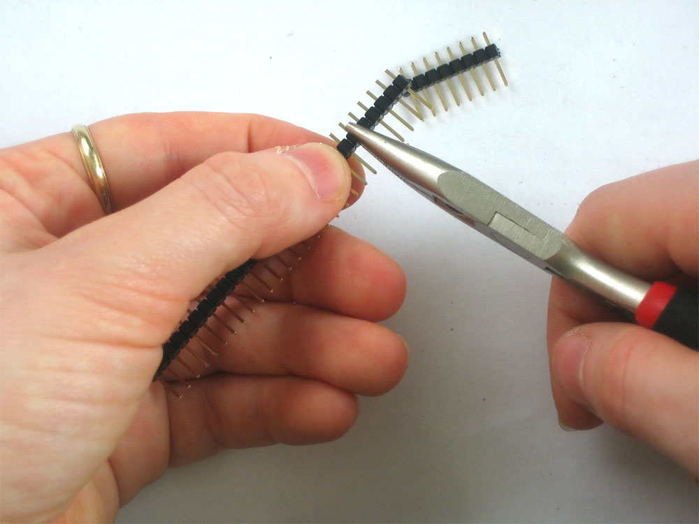
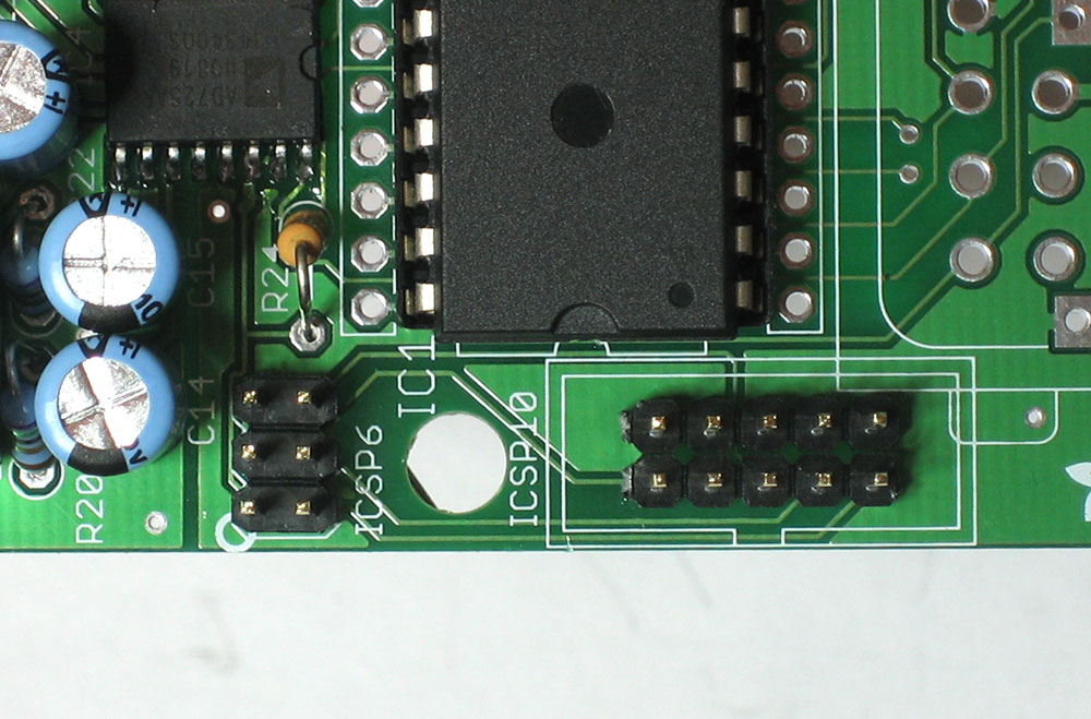
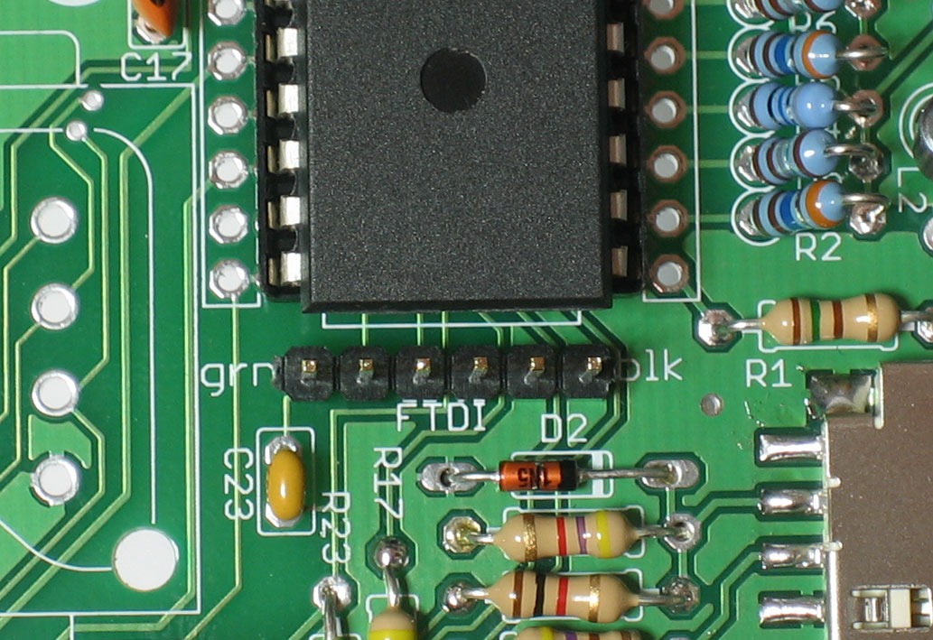
Next are the interface headers for programming. There are three different headers depending on how you want to program the Fuzebox. I suggest installing all three of them. Using pliers or diagonal cutters, clip off two 5-pin pieces and one 6-pin pieces of header. The 6-pin piece goes in the FTDI slot, next to one end of the microcontroller. The two 5-pin pieces go side-by-side in the slot labeled ICSP-10 There is also a piece of 2x3 header which goes in the ICSP-6 slot. The long end of the header goes up! Also, solder in C23 which is a capacitor that allows the 'auto-reset' hack to work (useful if you plan to program the Fuzebox with an FTDI cable) You may also want to place R24, which is a pullup resistor for the video chip's enable pin. In the latest versions of the Uzebox kernel, the ATmega's internal pullup does this job but if you happen to run into very old games it will keep you from wondering "why does the audio work fine but no video?" |
|
Solder in all the header. You may want to use a piece of tape to keep the header in place since the legs are too short to bend. |
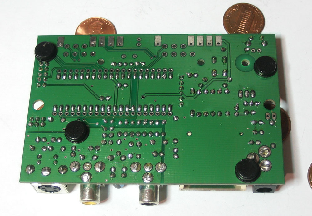 |
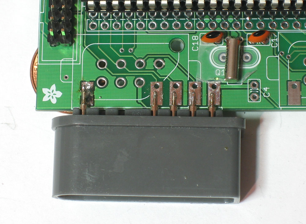
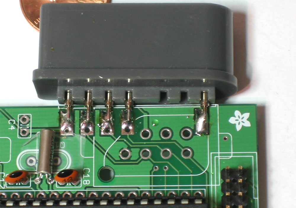
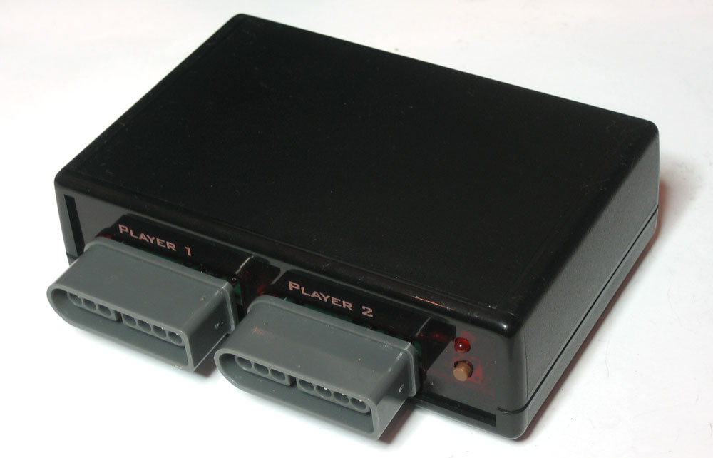
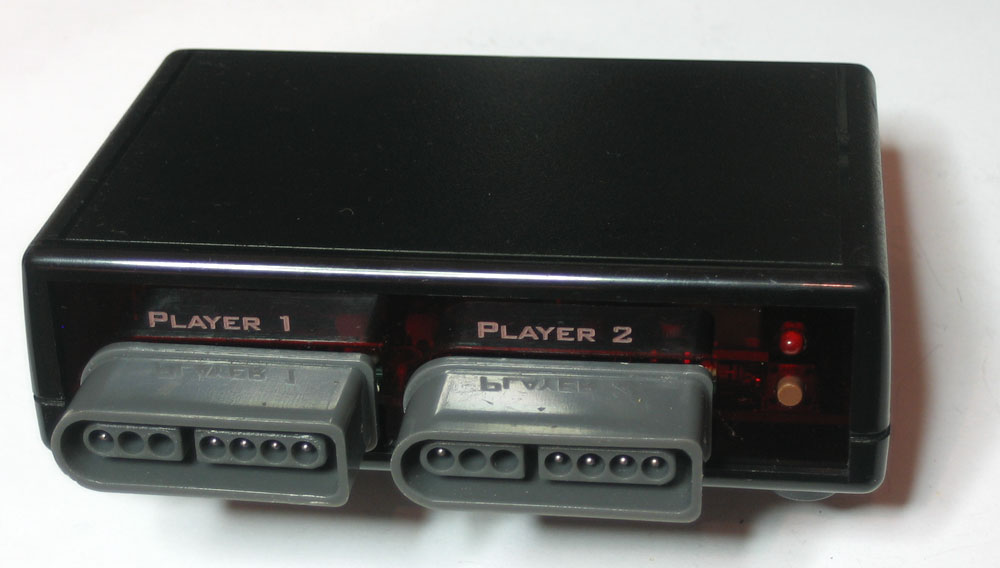
The final part is soldering on the SNES connectors. To prepare for that, place the four small bumpers that come with the kit on the bottom of the PCB. Also, find 4 pennies |
 |
Place the board on the pennies so that there is one underneath each bumper. |
|
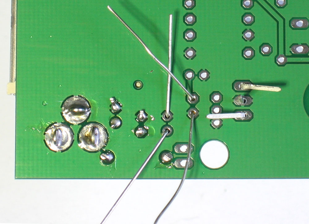
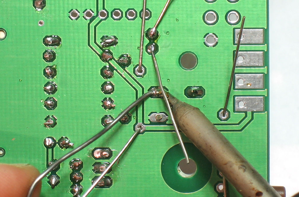
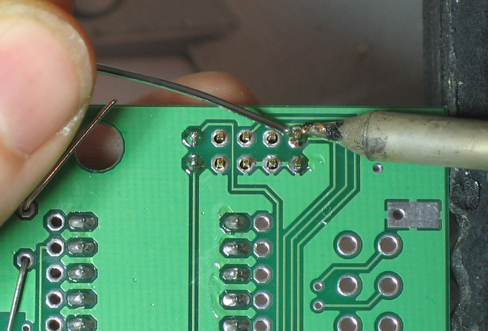
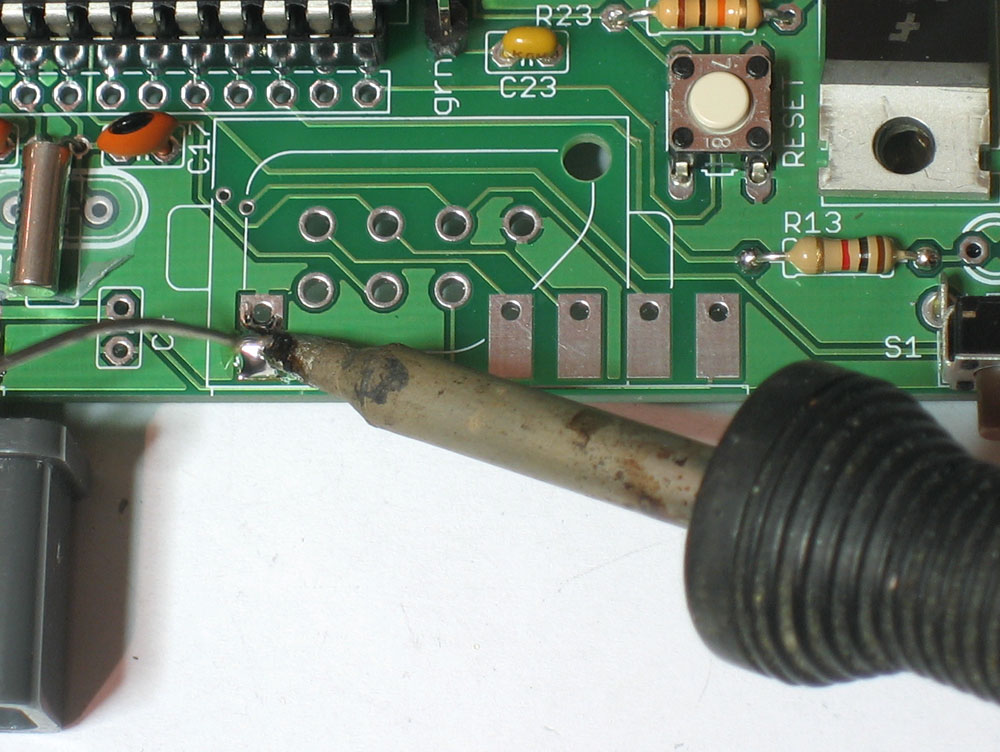
Start with the player 1 connector. heat up the leftmost pad and add some solder to it so there is a big bump of soldermelted on. |
|
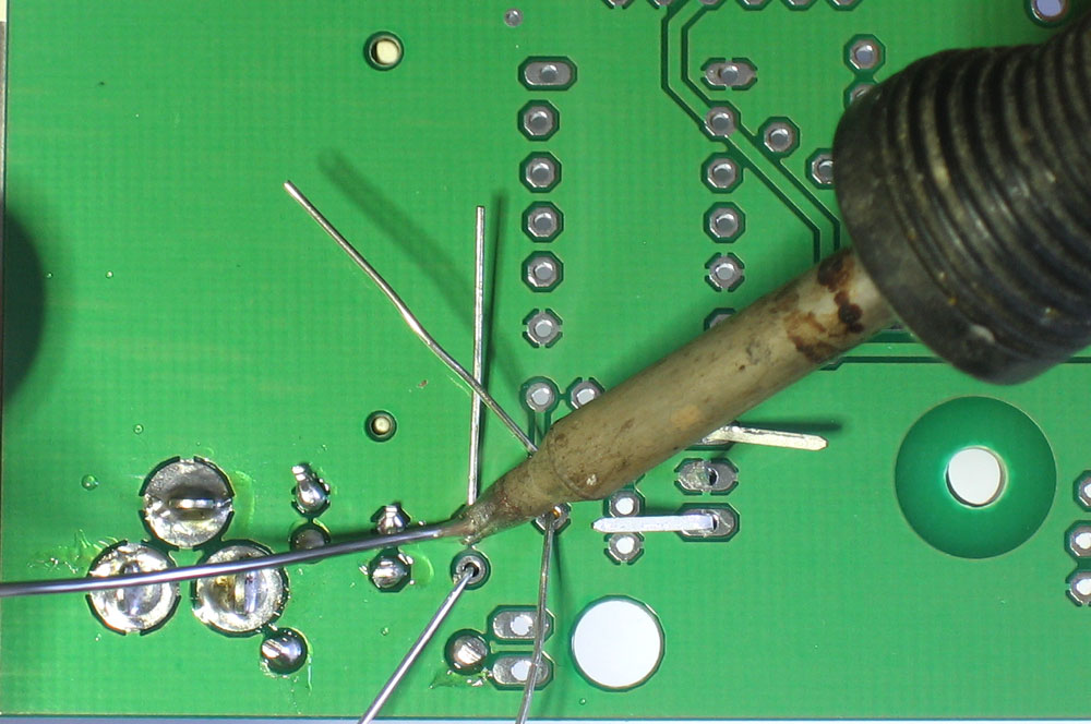
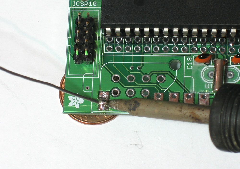
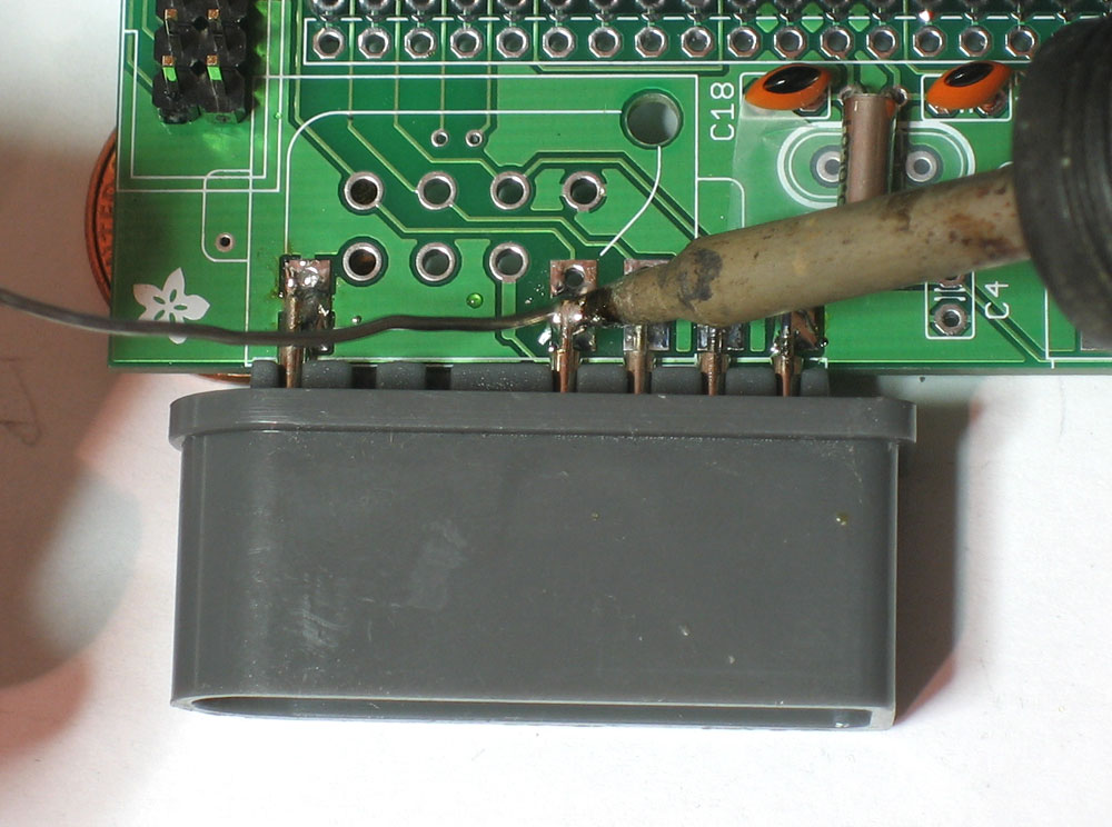
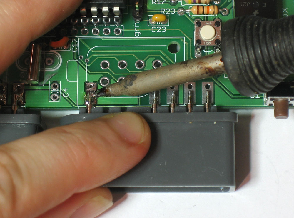
Now with one hand grab the SNES connector and heat up the bump of solder. Once the solder is melted and liquid, slide the SNES connector along the table so that the leftmost pin is right above the pad. Heat up the pin and pad so that the solder wicks onto it, making a solid connection. The connector should be flush against the edge of the PCB |
|
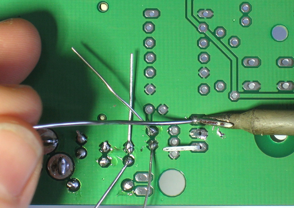
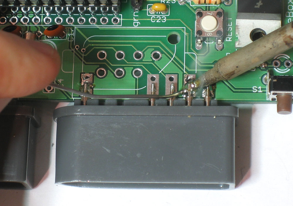
Now solder the four remaining connectors, using lots of solder to make sure there is a solid connection. Really, no matter how much solder you used, put double that amount on! |
|
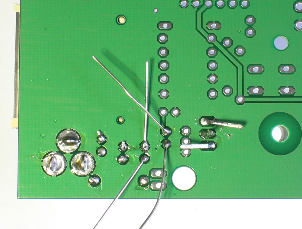
Repeat the process for the player 2 connector
Once you're done, solder in 0.1uF capacitor C4 (not shown) which is right between the two controllers. This is another bypass cap that will keep the power supply steady when the controllers are used! |
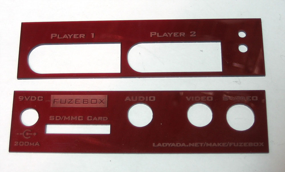 |
The next few steps assume you are going to place the kit in the matching enclosure. If you're not, then simply follow the step for the LED but solder it flat against the PCB. Find the two enclosure plates, and peel off the backing if youd like (it will look a little better) |
|
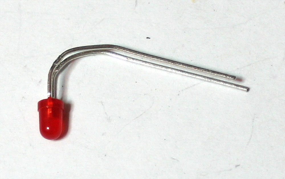
Bend the 3mm red LED so that it will sit above the front button. Note that one leg is longer, this is the positive (+) leg. Solder in the LED so that it sits above the button. The longer lead (+) goes in the pad/hole next to the 1K resistor. Don't worry if the LED isn't positioned perfectly right now, just make sure you have enough slack to move it around. |
|
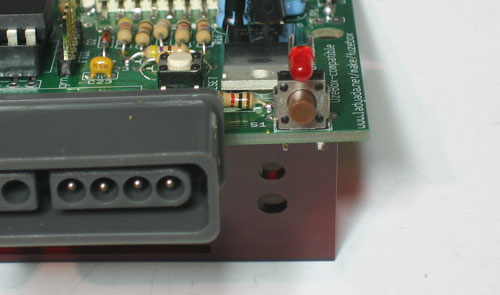
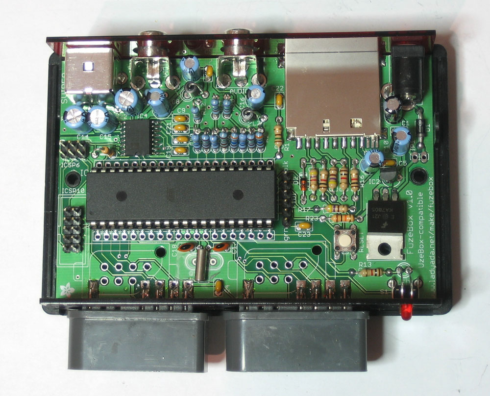
Place the front plate over the SNES connectors (it may take a little wiggling. Then bend the LED so that it fits through the hole above the button. Then place the rear panel on, and set all three into the bottom of the enclosure. The PCB should snap into the two round bosses. The plates fit into the grooves inset into the case. |
|
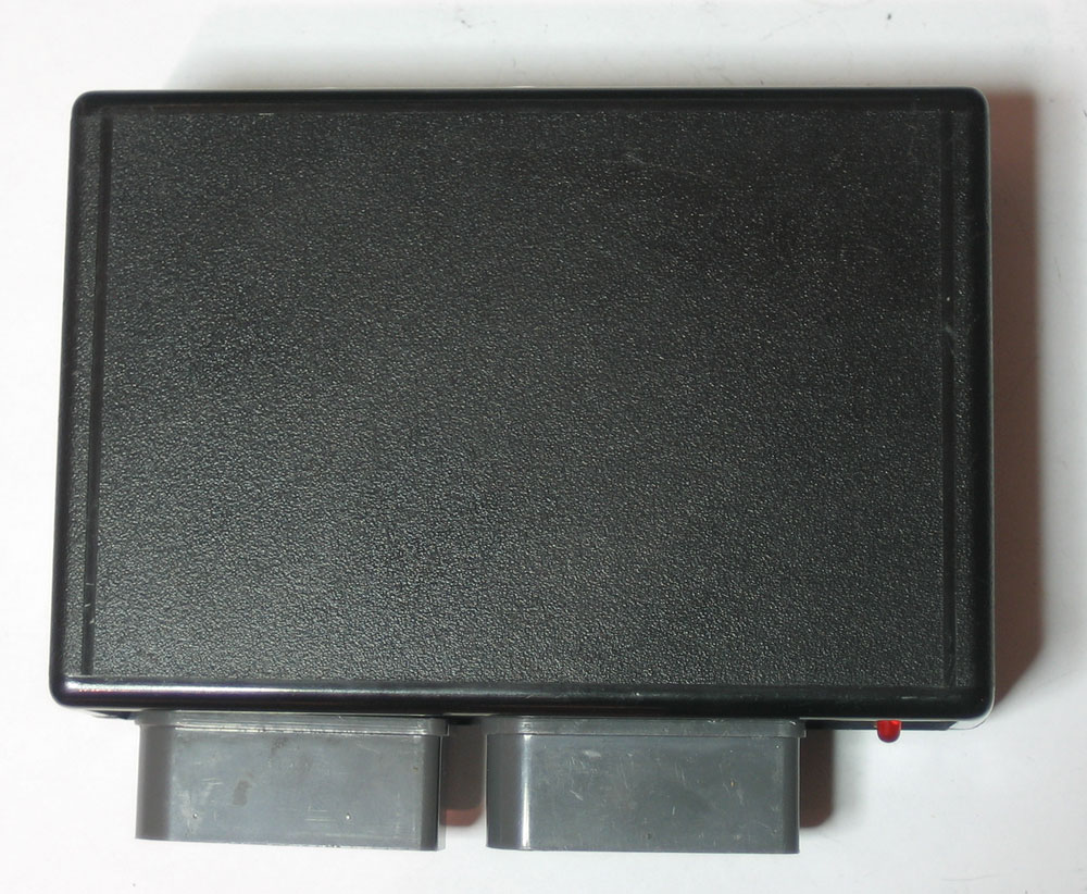
Finally, you can place the box top on. The enclosure has two tabs, one oval and one square, so look out and make sure they line up properly or the box wont close! Don't screw it in place yet, you'll want to test it out and perhaps program in a game first |
|
You're done! Now its time to read the user manual to learn how to upload games and design your own. |