|
|
|
Fabrication |
history
last edited:
September 22, 2004
|
| Building
a MiniPOV (For the student) |
|
|
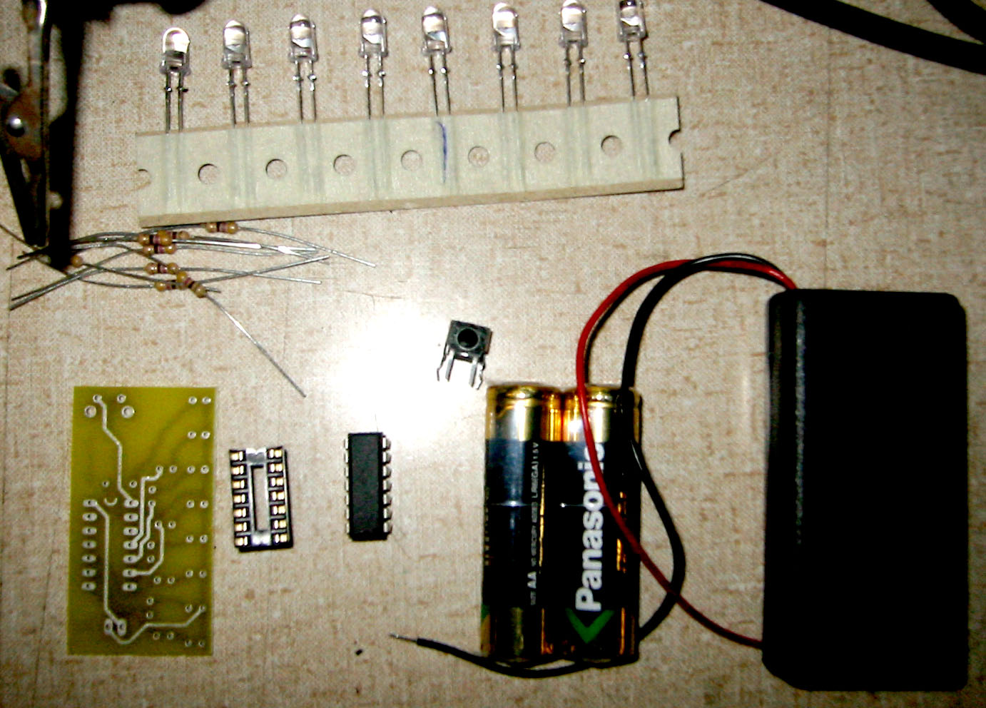
- Aqcuire all the parts (shown here in a plastic bag), a soldering
iron of reasonable quality, rosin core electronics solder, angle
cutters (not shown), and preferably something that can hold the
PCB while you solder. A vise or 'handy hands' tool (on the left)
will be fine.
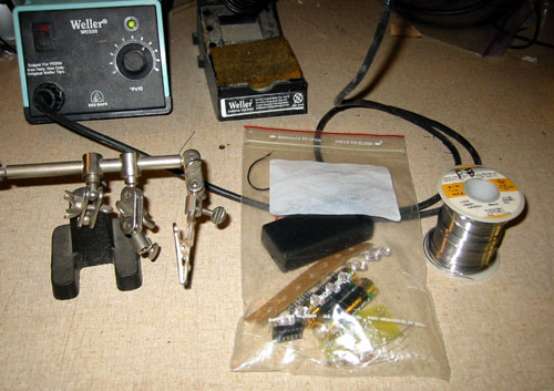
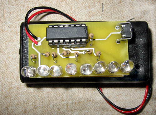
- Lay out the parts on the table, identify all of them. Clockwise
from the top: 8 LEDs, battery holder, 2 batteries, switch, 14-pin
microcontroller, matching socket, PCB, and 8 resistors.
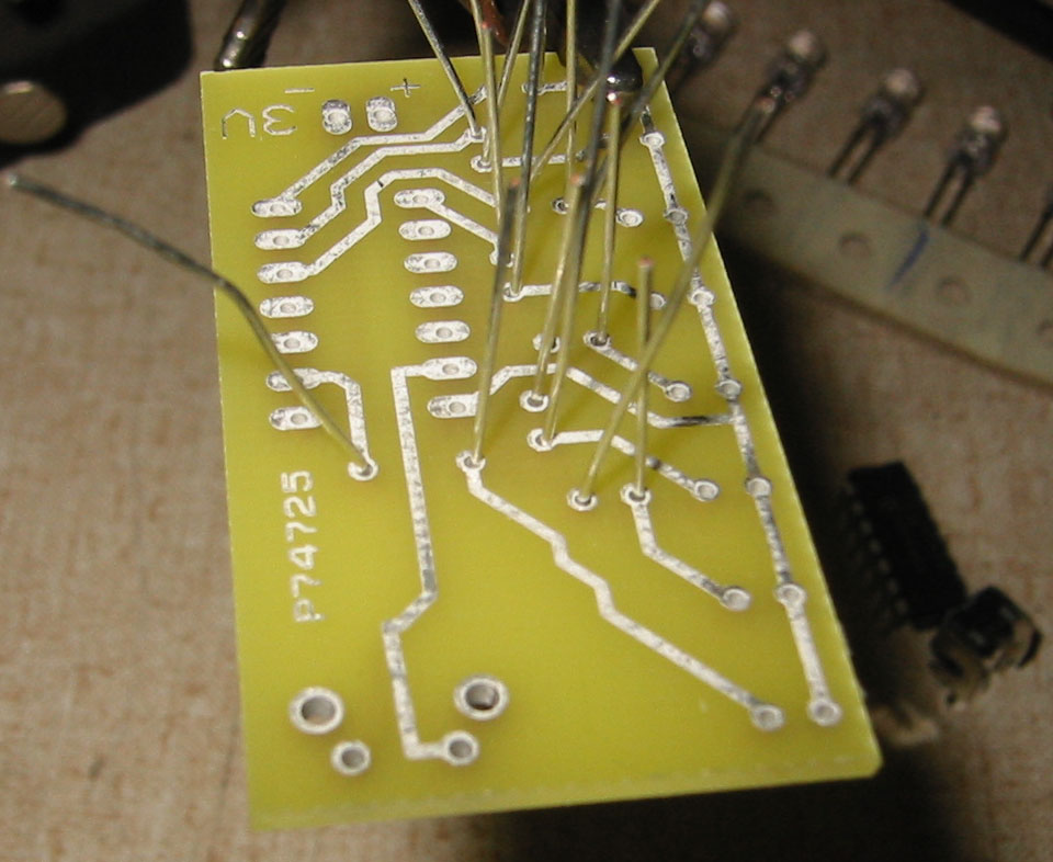
- Place the PCB in the holder so that the correct side (shown
here) is facing up. Bend all the resistors into U-shapes and insert
them into the proper holes. There is no orientation to resistors
and they are all the same type. Bend the leads out a little so
that when you flip the board over they don't fall out.
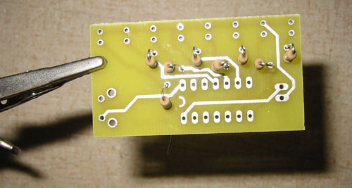
- Flip the board over, as shown, and solder all the leads. Then
clip them close to the board using the angle cutters

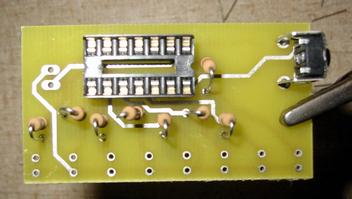
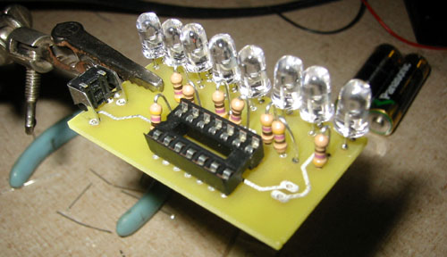
- Turn the board back over, place the socket as shown, with the
notch on the same end as the imprinted "U" on the board. Place
the switch also. Turn the board over and solder both to the PCB.
You don't have to clip any of the leads unless they seem too long.

- Next is the LED placement. LED's are polar, and if they are
put in backwards they won't light up. Looking down at the LED
you will see one side is flattened. The flat side is the side
that is closest to the board edge when placing the LED. That side
is also the side that, if the LED is clear, you can see a 'cup'.
 Place all 8 LEDs, making sure they all oriented correctly!
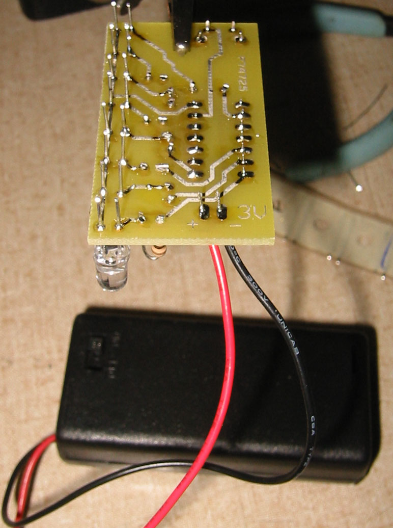
- Turn over the board, solder the LEDs, and the battery pack
wires, taking care to connect the red wire to the + terminal and
the black wire to the - terminal. Clip the LED leads close to
the board, as well as any excess wire.
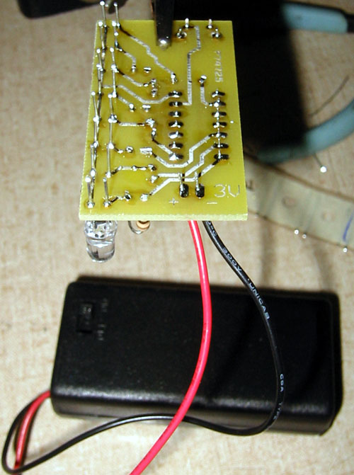
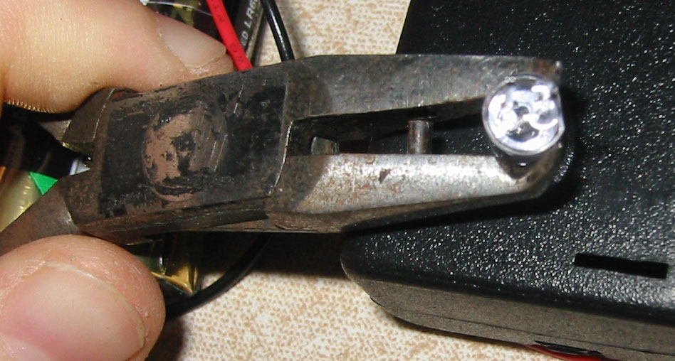
- Place the microcontroller in the socket, matching up the notches.
Install both AA batteries. Use hot glue, epoxy, double sided tape,
etc, to attach the PCB to the battery holder. You're done! Turn
it on!
|
|
|
|
|
| Building
a MiniPOV (for the instructor) |
|
|
You'll need to decide what to have the MiniPOV display and then
program that into the microcontrollers you give out. Download the
asm source code. Try to understand it. The image map is stored at
the bottom. You'll also have to change the value in the loop that
defines the number of lines in an image. This is defined at the
top in IMAGESIZE. Then you have to make sure that the timer code
jumps to your imagemap. Vers 1.0 jumps to EC so change that if you're
going to name your imagemap something else.
Once you've done that, use MPASM and a PIC programmer to program
all the 16F630. (Start with one, test it fully, then go on to the
next) In case your programmer can't read the fuses from the HEX
file, they should be: MCLR off, Internal RC with no clockout, code
protect off, EE protect off, powerup timer, no brownout detect,
no watchdog timer.
The button doesnt do anything yet, feel free to use it to change
messages/images, or something.
|
|
|
|
|
|