These are the instructions for v2.0, if you have an older mintyboost you may want to check out the specific instructions for version v1.2 (white PCB with v1.2 marking), versions v1.1 (green PCB with v1.1 marking on the back and on the kit packaging) , version 1.0 is basically the same as v1.1 so just follow those instructions
The first step is to solder the kit together. If you've never soldered before, check the Preparation page for tutorials and more.
Some web browsers (basically, IE) do not like my website so much and load the photonotes slowly. So, if you are wondering where the rest of the instructions are, either wait a while and IE will eventually display it (below here). Or download Firefox/Safari which does not have this problem!
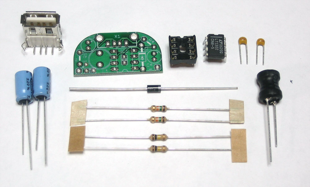 |
Check the Bill of Materials to verify you have all the parts necessary to make the kit. (The battery holder isnt shown here) |
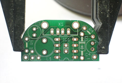 |
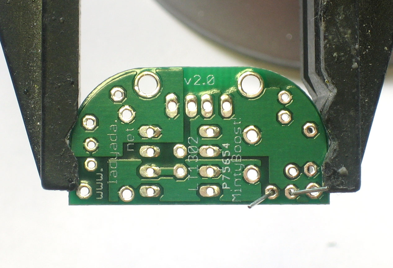
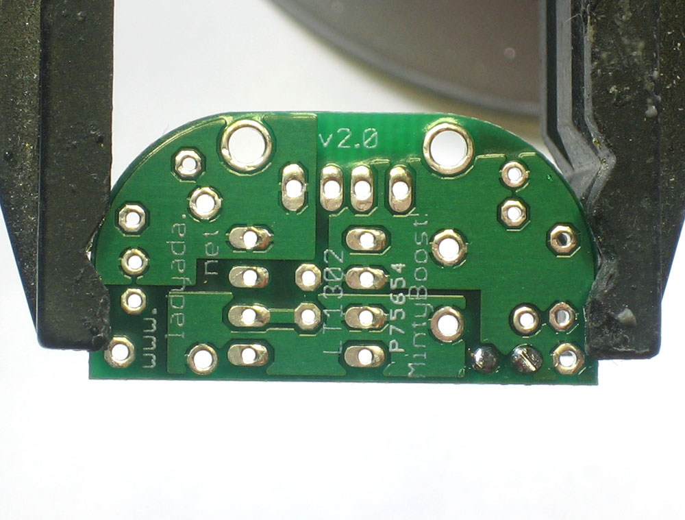
Place the PCB in a vise, and turn on the soldering iron. Make sure you have all the tools you'll need to assemble the kit. |
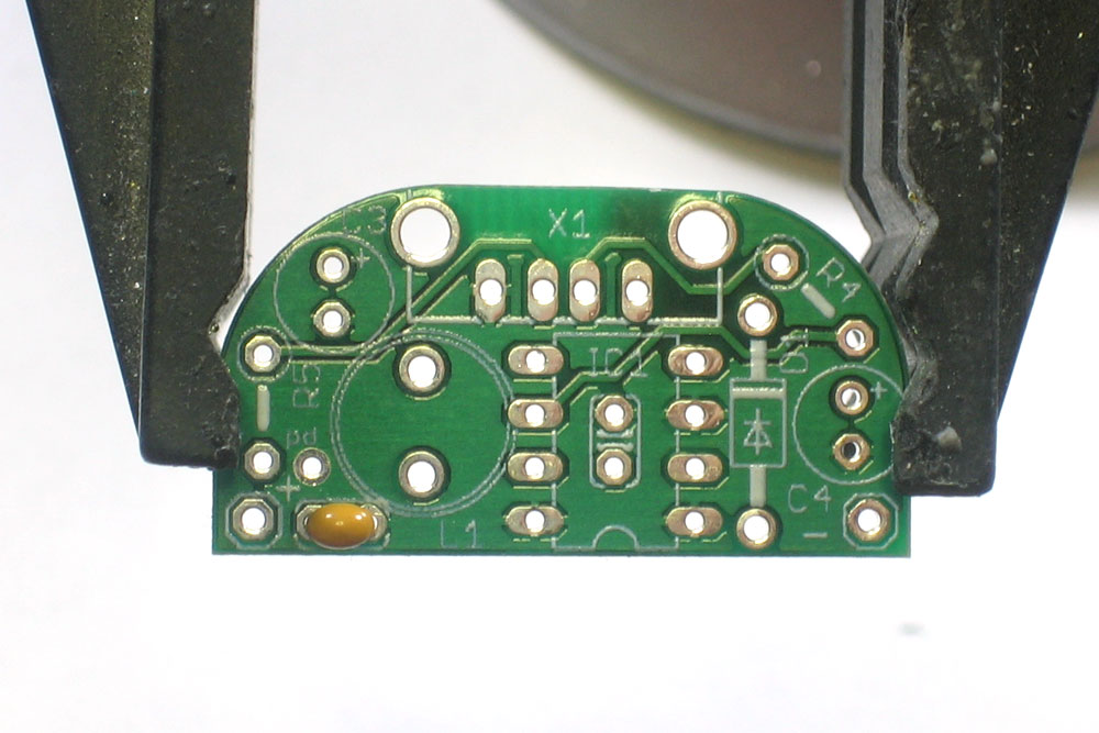 |
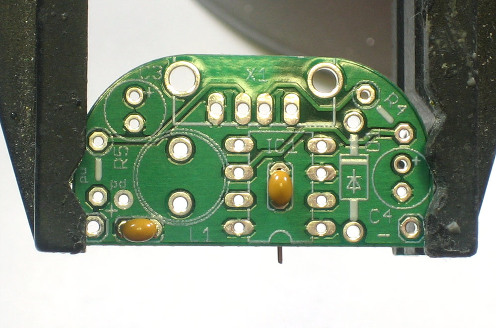
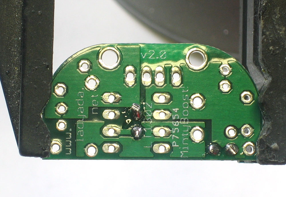
The first component we will place is the small yellow ceramic capacitor C1. Ceramic capacitors have a nice property that they are symmetric/non-polarized. That means they can go in 'either way'. Place the capacitor so that the 2 legs (leads) slide thru the two metal holes in the PCB (pads). The capacitor will sit flat against the PCB. This capacitor helps stabilize the output voltage, and filters out high frequency noise so that the 5V output is nice and smooth. |
 |
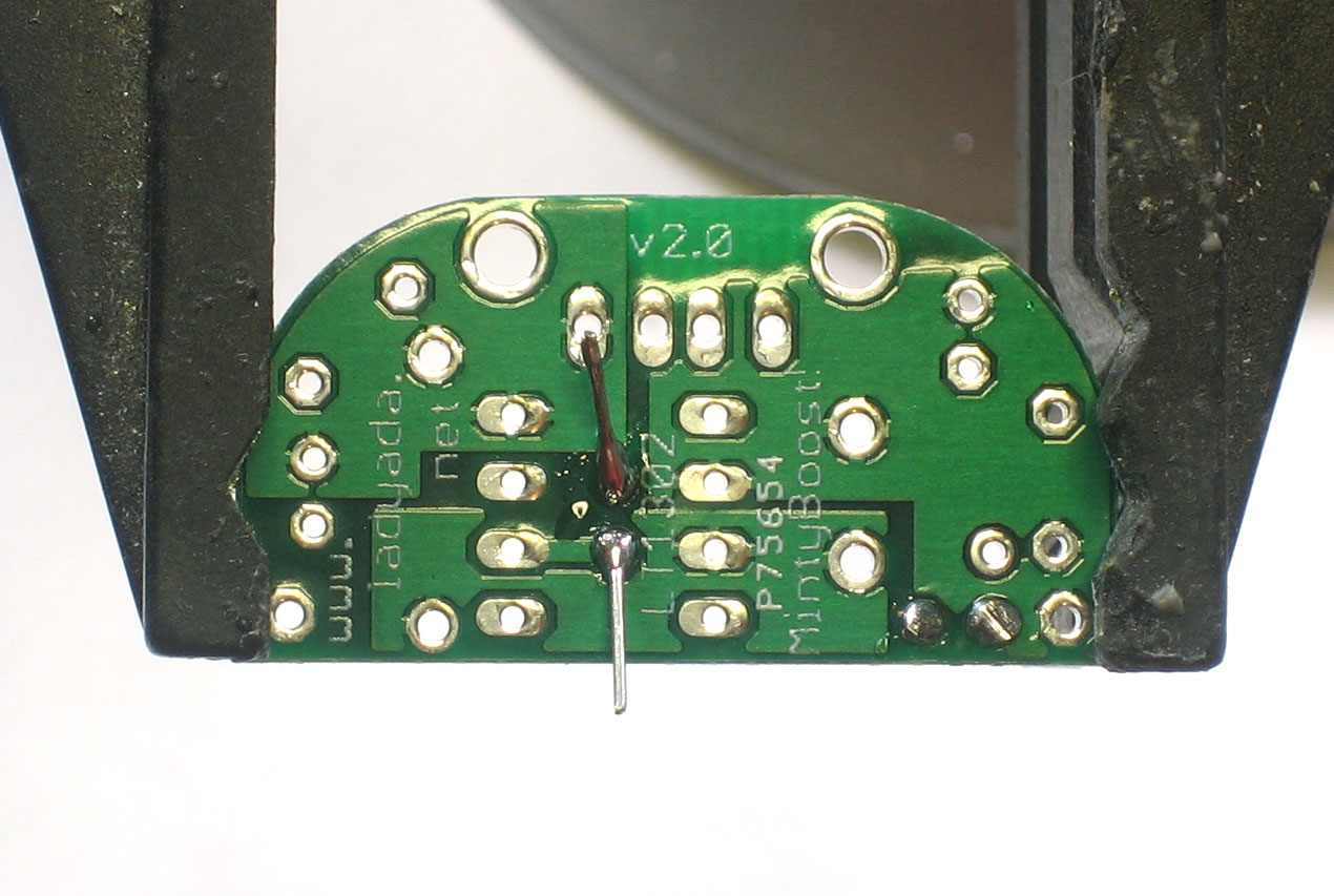
Bend the little leads out so that you can flip over the PCB and the capacitor will stay in place. |
 |
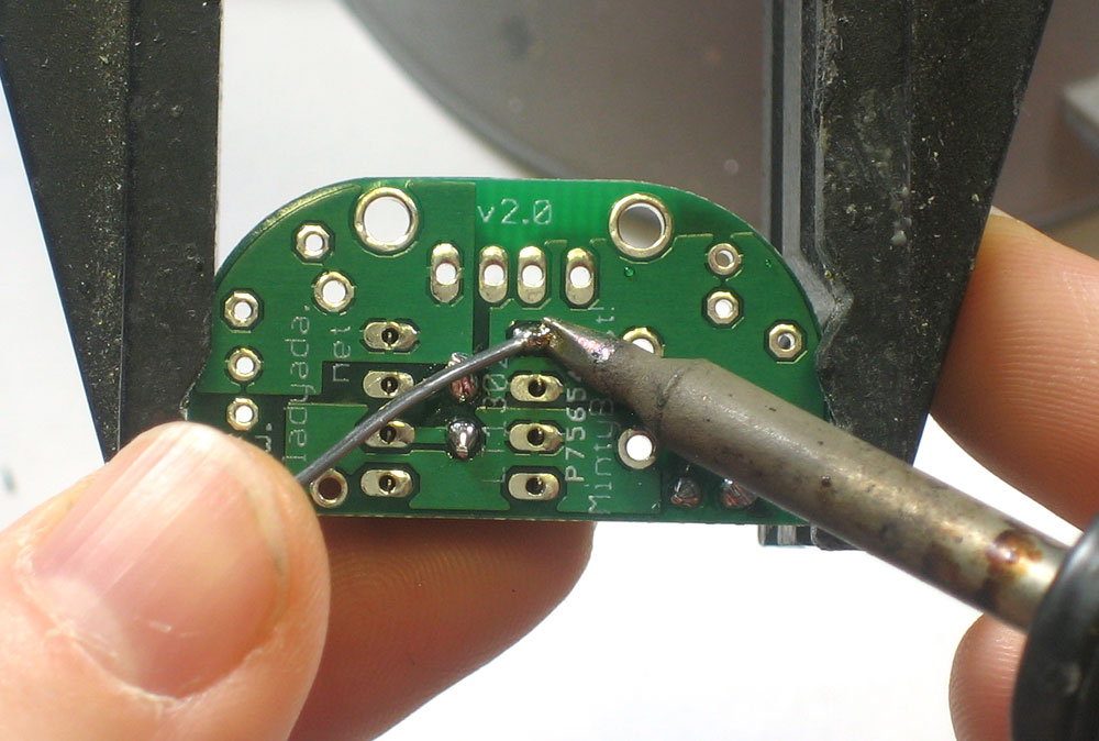
Place the flat of the soldering iron tip against the silver ring (pad) and one of the wires of the capacitor (lead) at the same time for 2 seconds. This will heat them both up to 600-700 degrees. Then poke the end of the solder so that it flows into the hole and forms a solder joint |
 |
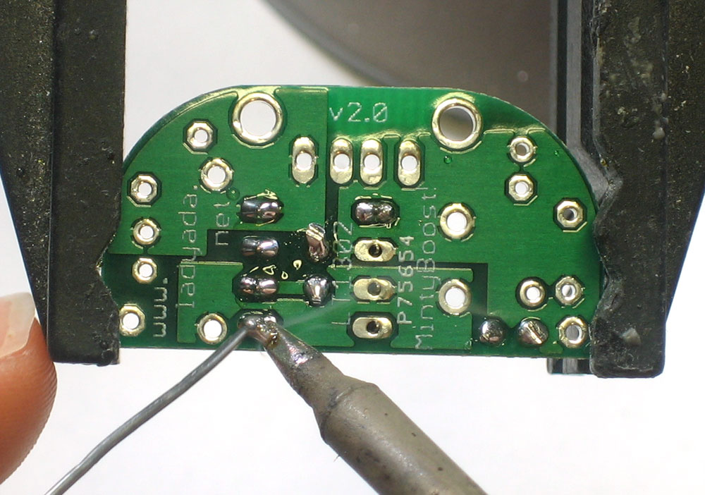
Do the same with the other pad and lead. |
 |
The solder joints should be full, smooth and shiny. |
|
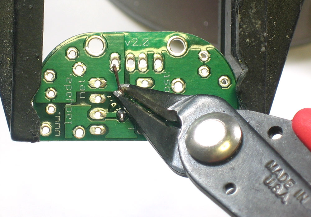
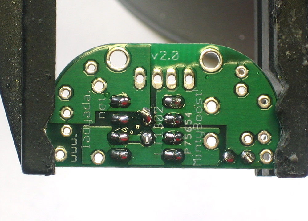
Now it is time to clip off the excess wire from the leads. using the diagonal cutters, clip off the wire just above the solder joint. |
|
Now its time for the next capacitor, C2. This capacitor is used to stabilize the internal reference of the boost converter chip. This keeps the chip stable so that it will generate a voltage as precise as possible. |
|
Solder the capacitor just like the other one |
|
Clip the capacitor leads |
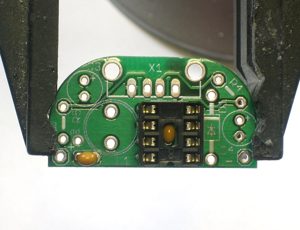 |
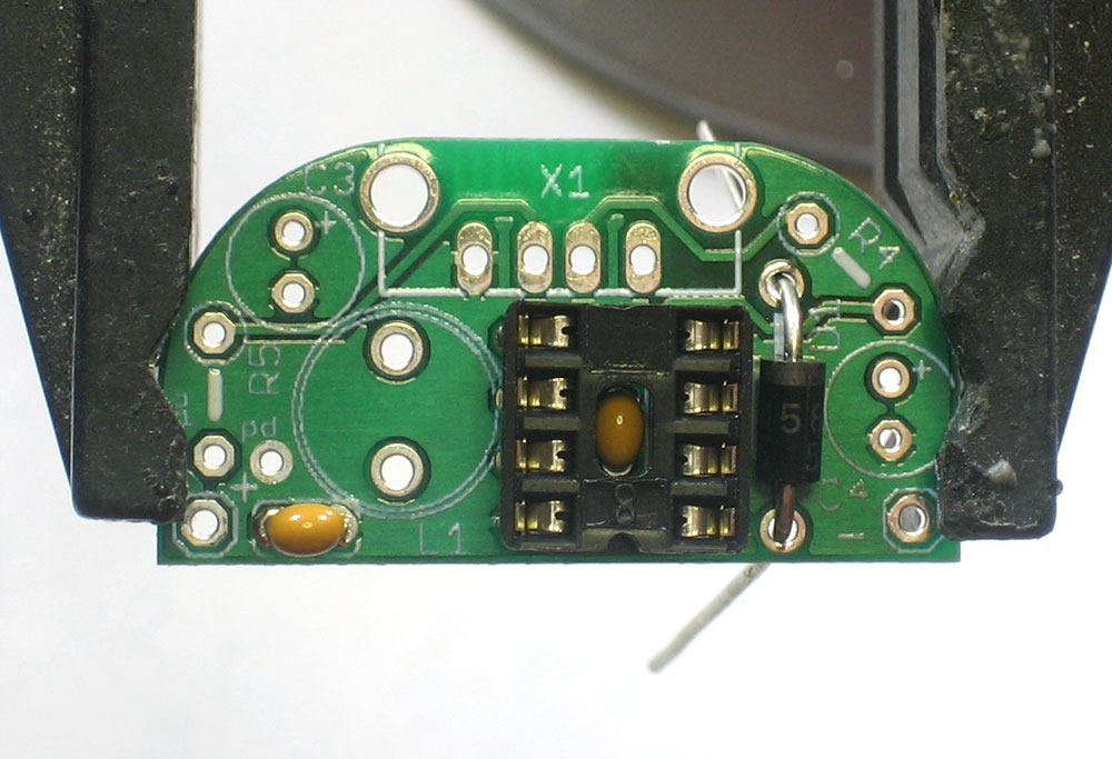
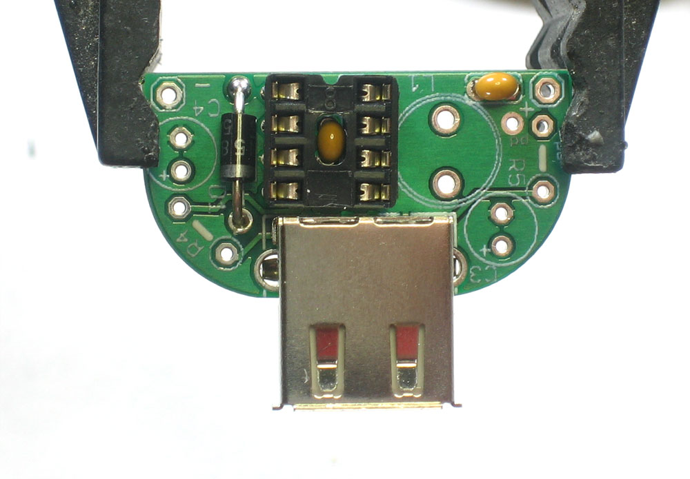
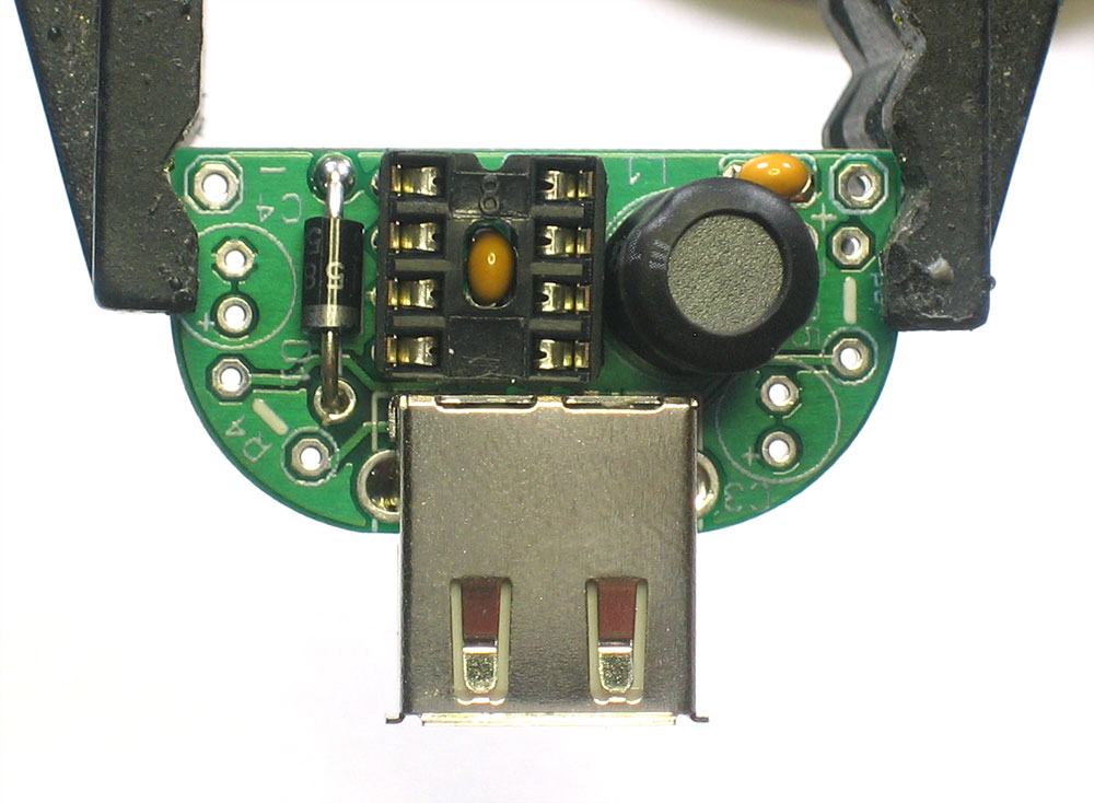
Next is the IC socket. This protects the chip and allows you to replace it if there are any problems. The socket goes over the ceramic capacitor but the capacitor should not interfere as long as it was soldered in properly. Make sure you solder the socket in so that the notch in the edge of the socket matches up with the notch in the silkscreen image of the socket. In this image its near the bottom. If you mess this up, dont try to desolder the socket, instead just keep going and remember that it is upside down later when its time to install the chip |
|
The socket has short legs so it can be annoying to keep in the right position. hold it in place with one finger and 'tack solder' a corner. Once that is done, solder in the remaining 7 pins. There is no need to clip. |
|
Next is the schottky diode D1. This diode is part of the boost converter. Essentially it is used to make sure energy is transfered in only one direction-from the batteries to the USB port. Diodes have a special property that current can only pass thru them in one direction. That means that it is important to make sure that they are not inserted in backwards. Examine the diode and find the end with a white stripe. This stripe should match up with the silkscreen image, which also has a stripe on one end. In this image, it is towards the top. |
|
Solder and clip the diode. |
|
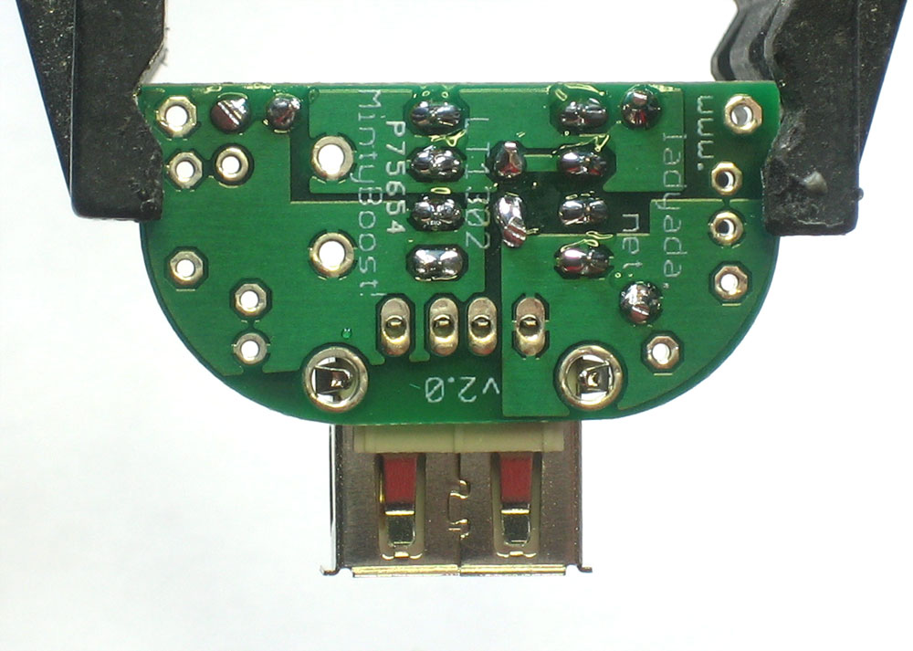
Next is the USB type A connector. This is the connector that is on a computer, and nearly all USB charging cables will plug into it. The Connector should snap easily in place. |
|
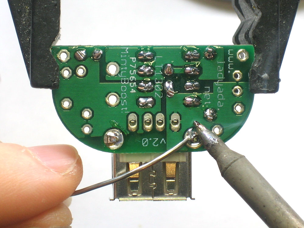
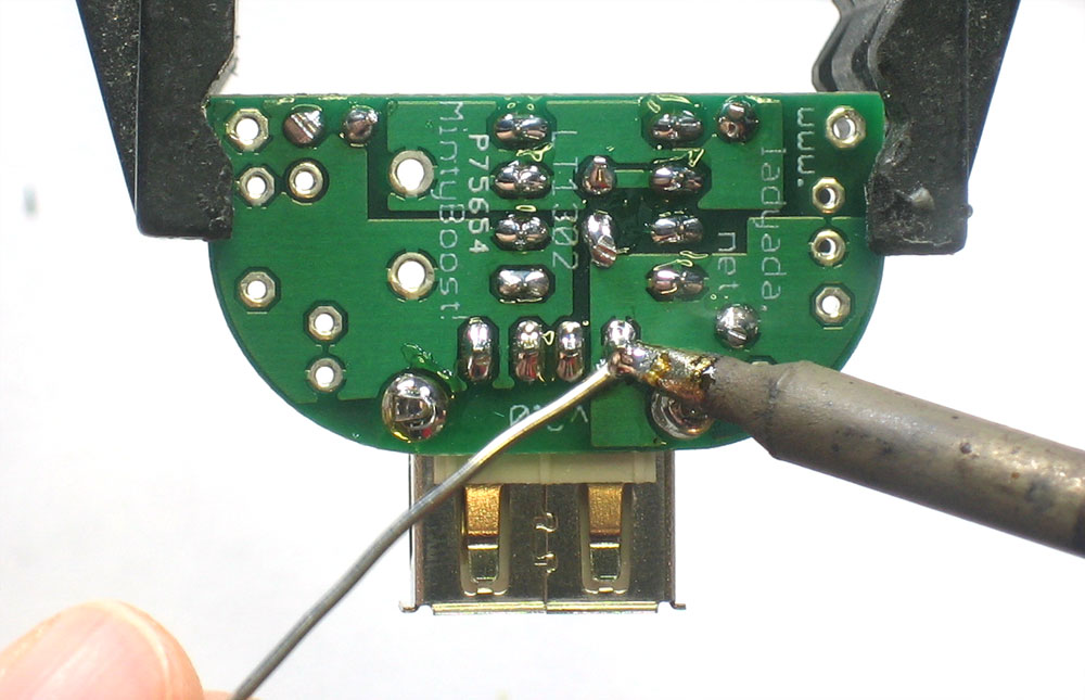
The two large side connectors are used for mechanical strength. They keep the connector attached solidly to the PCB so make sure to use lots of solder or it will break off from use. The four middle pins carry the power and data for USB. Solder in all four. |
|
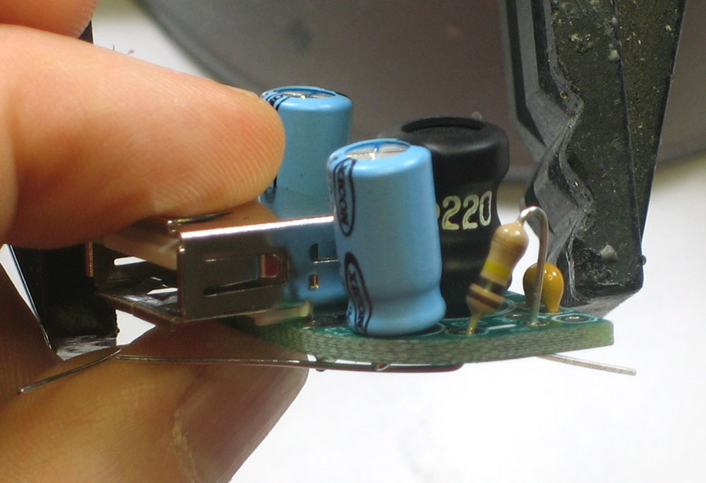
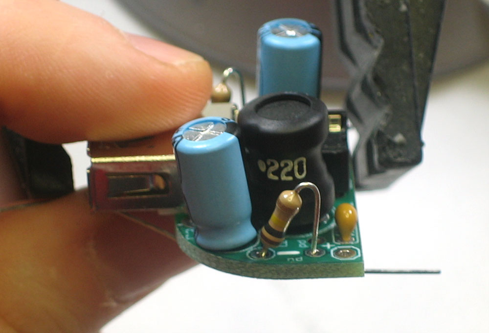
Next is the power inductor L1. This component is used by the DC/DC converter chip to store and convert power from low voltages to high. Inductors are just a coil of wire so they have no polarity and can be placed either way. |
|
Solder and clip the inductor leads |
|
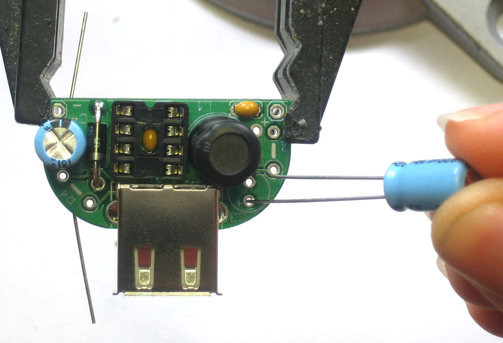
Next are the two electrolytic capacitors. These help smooth both the input and output voltages, to keep them stable during the up-conversion. They are used for low frequency noise, and are often paired with a ceramic capacitor. Electrolytic capacitors are polarized and must be placed correctly or the circuit will not work. The longer lead is the positive (+) one and must go into the pad marked with a + as shown |
|
Solder and clip the two capacitors |
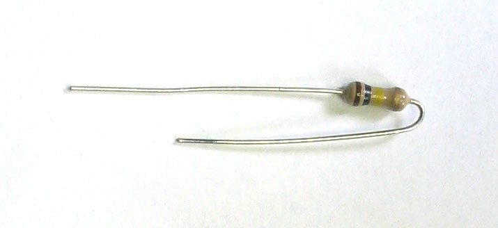 |
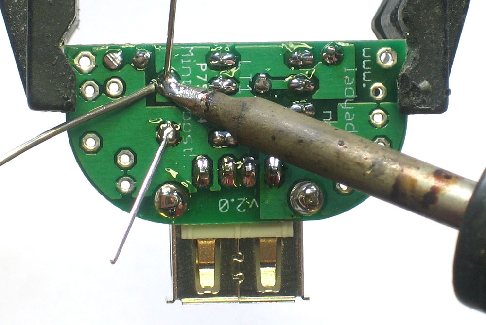
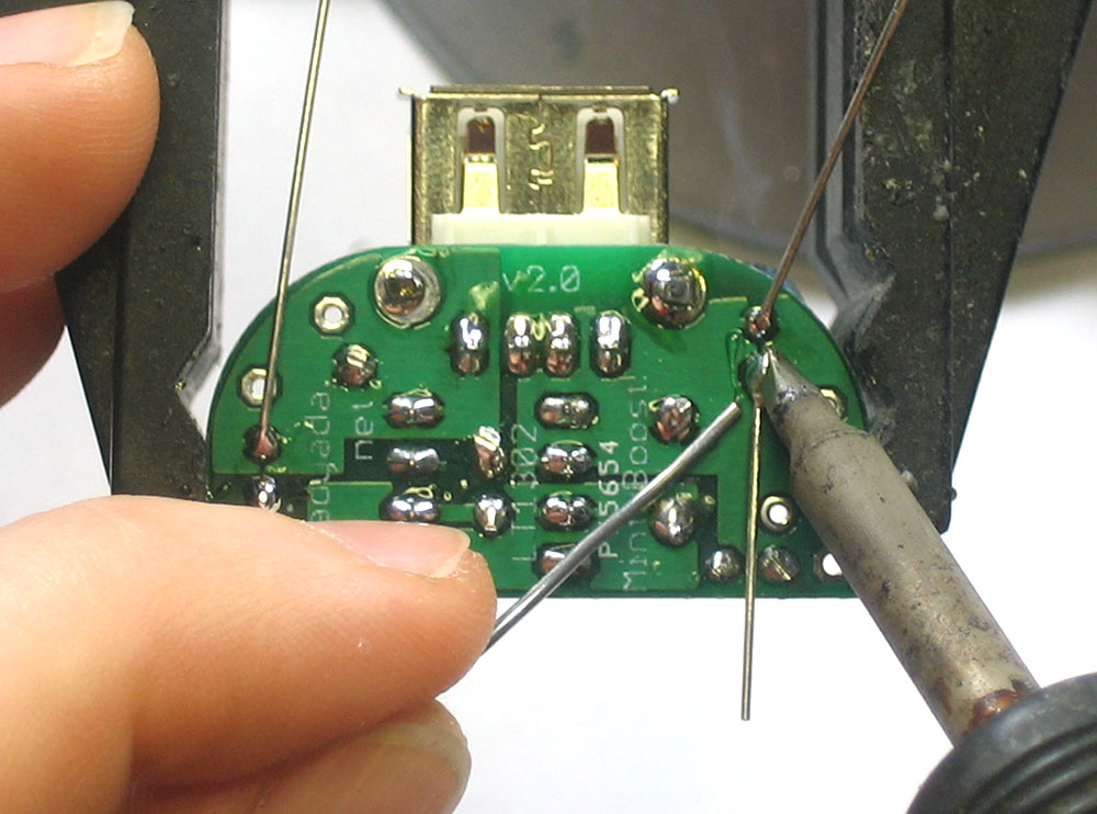
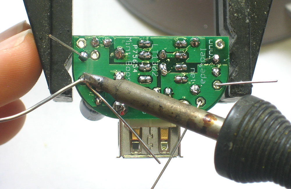
Next it is time to solder in the two resistors that will be used to bias the data lines. This is necessary because many devices use the data lines to indicate whether there is a charger attached or a computer. Since there is no standard every manufacturer uses, there is no guaranteed way to make sure a charger works with every device. However, after some testing, it has been determined that, especially with Apple products such as the iPod/iPhone/iTouch, 2 100K resistors in a 'pull up' configuration seem to do the job. For older devices, 15K was used. Some also like one of the datalines pulled down. We will show how to install the most common configuration and leave it up to you if you'd like to do something else. Bend the two 100K resistors into U shapes. |
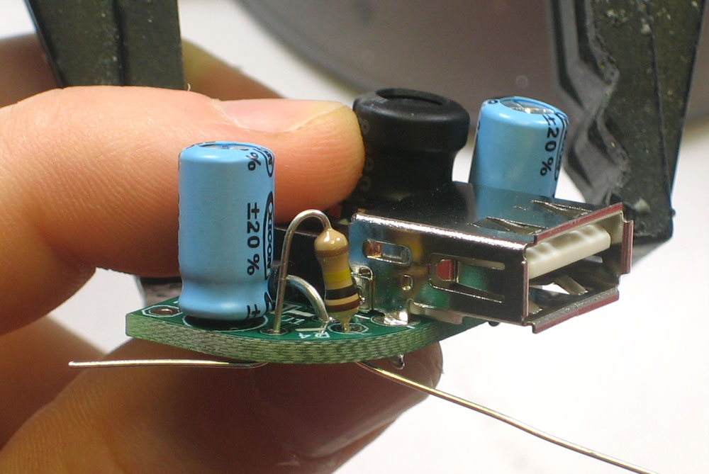 |
The first resistor, R4, goes to the right of the USB connector as shown. |
|
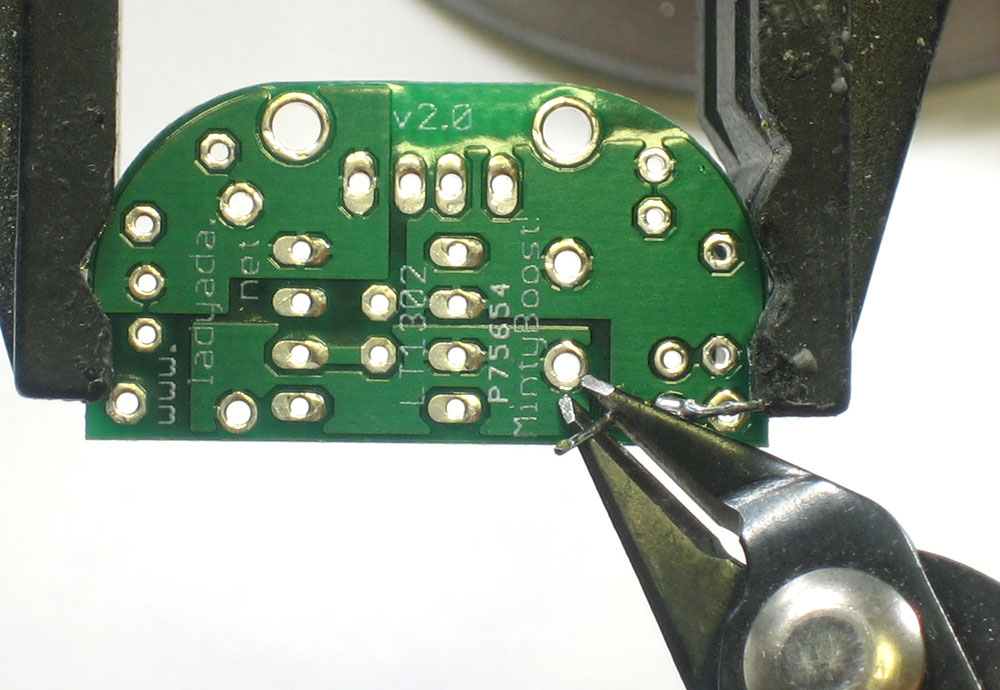
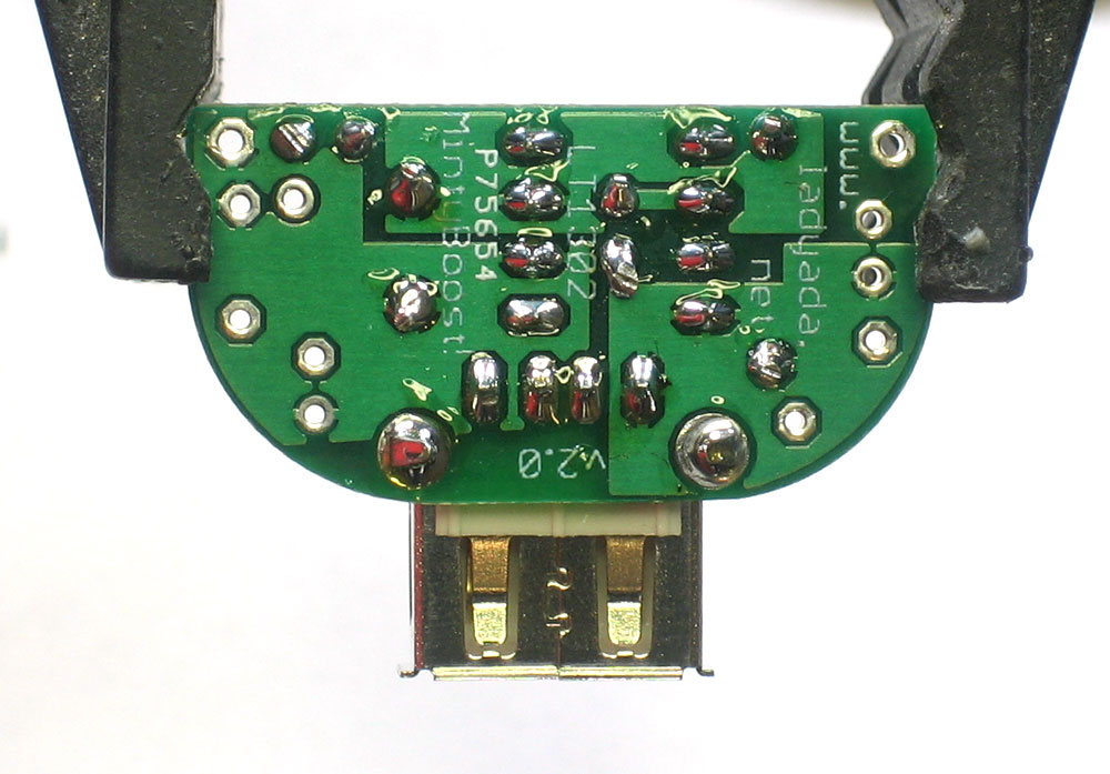
The second resistor R5 goes in to the left of the USB connector as shown. there are two holes that the wire lead can go thru, one is marked with a line and a small "pu" (pull up) and the other hole is plain and is marked with a small "pd" (pull down). Use the one marked "pu" |
|
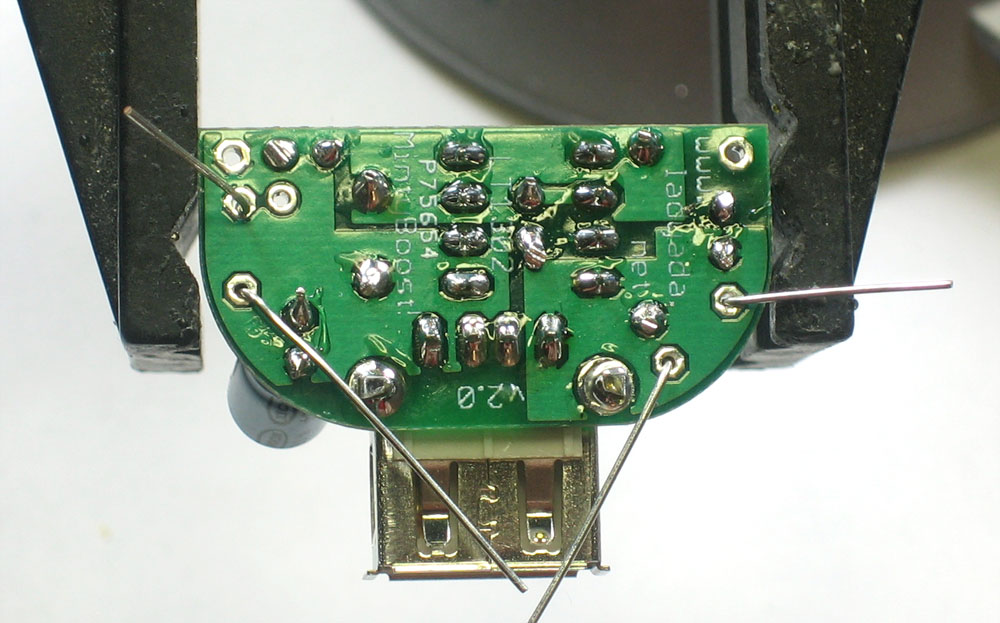
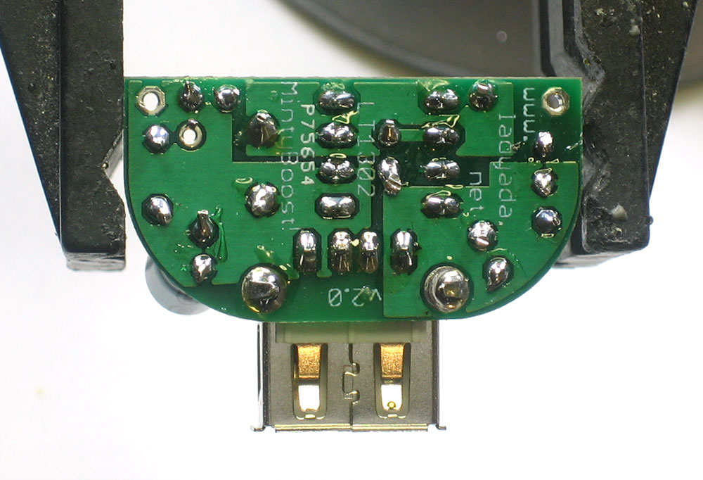
Solder and clip the two resistors |
|
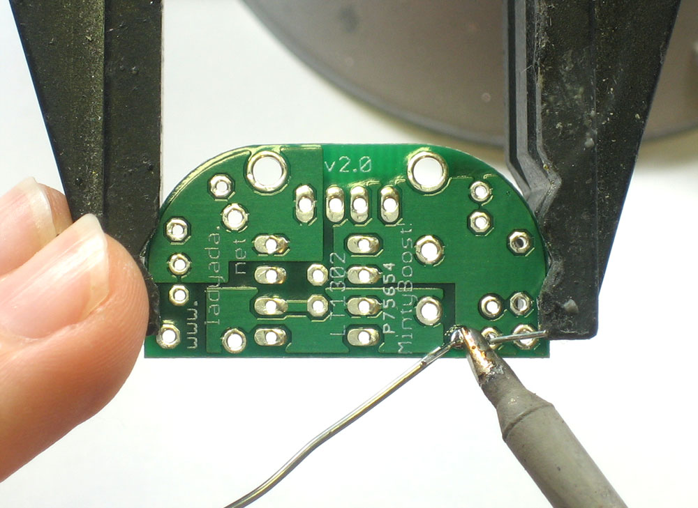
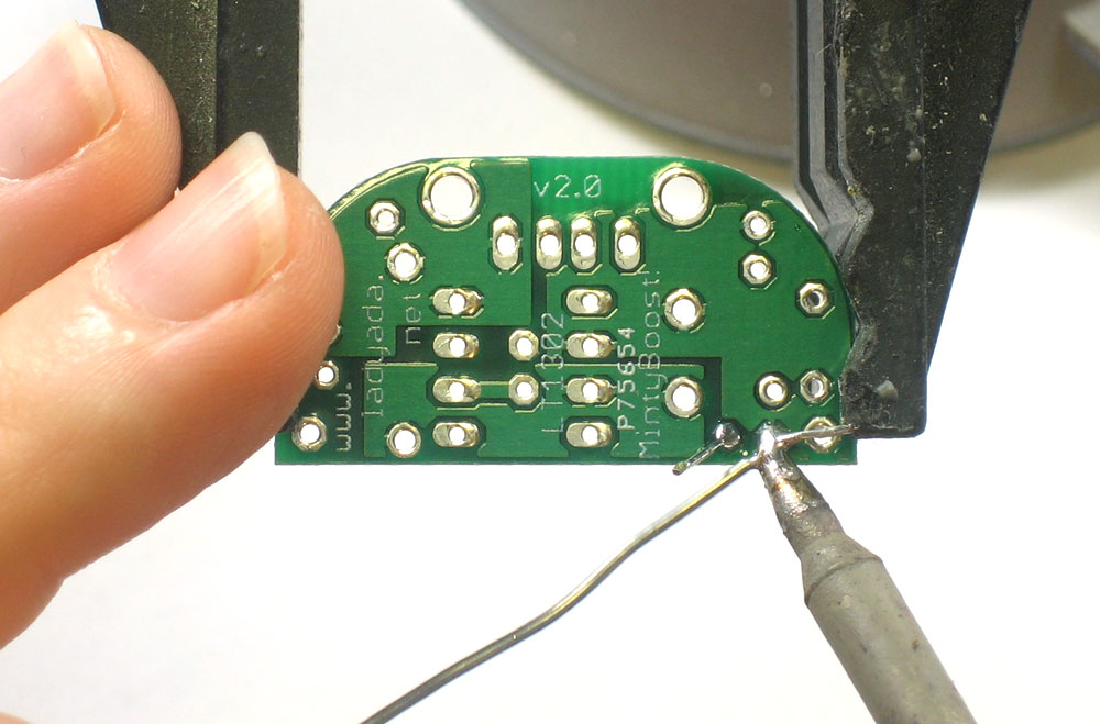
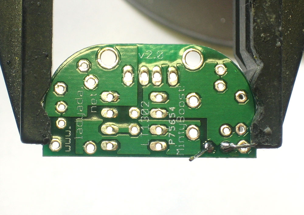
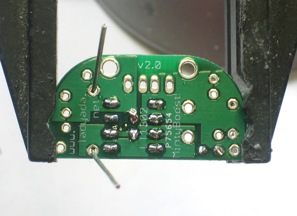
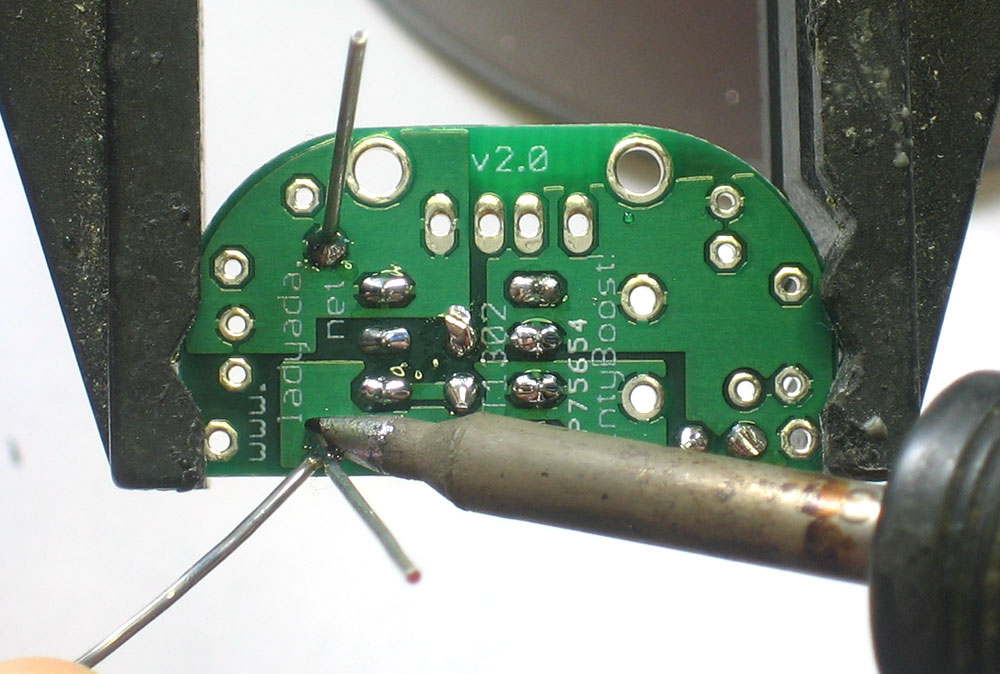
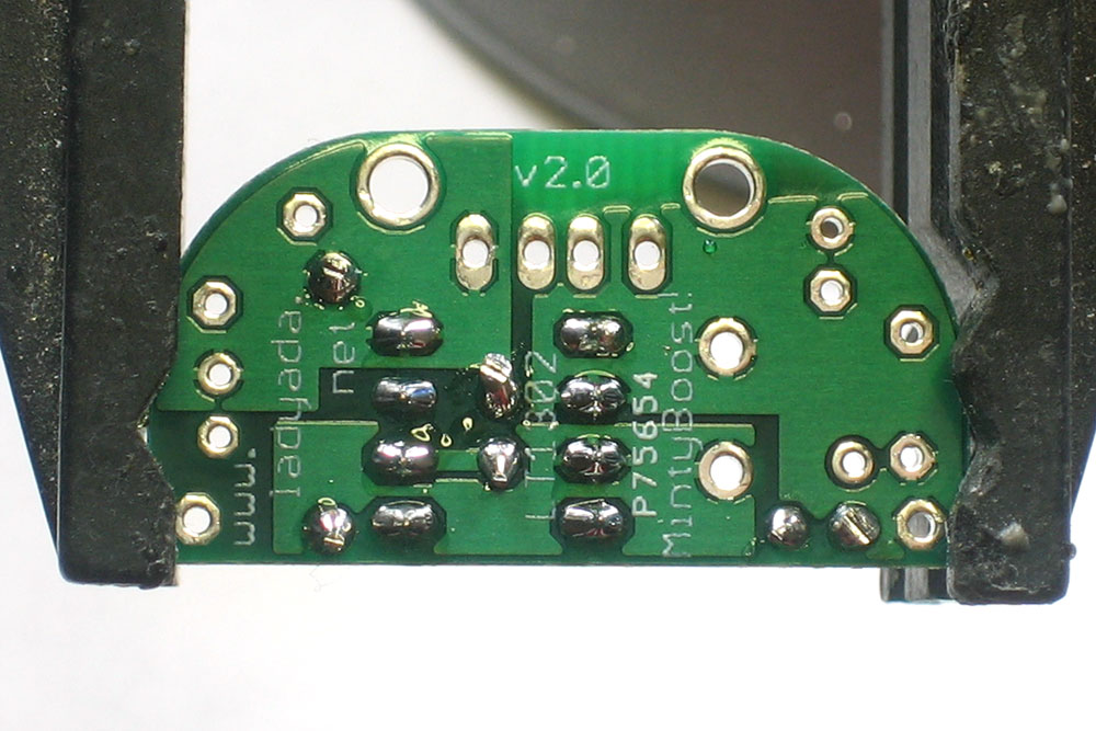
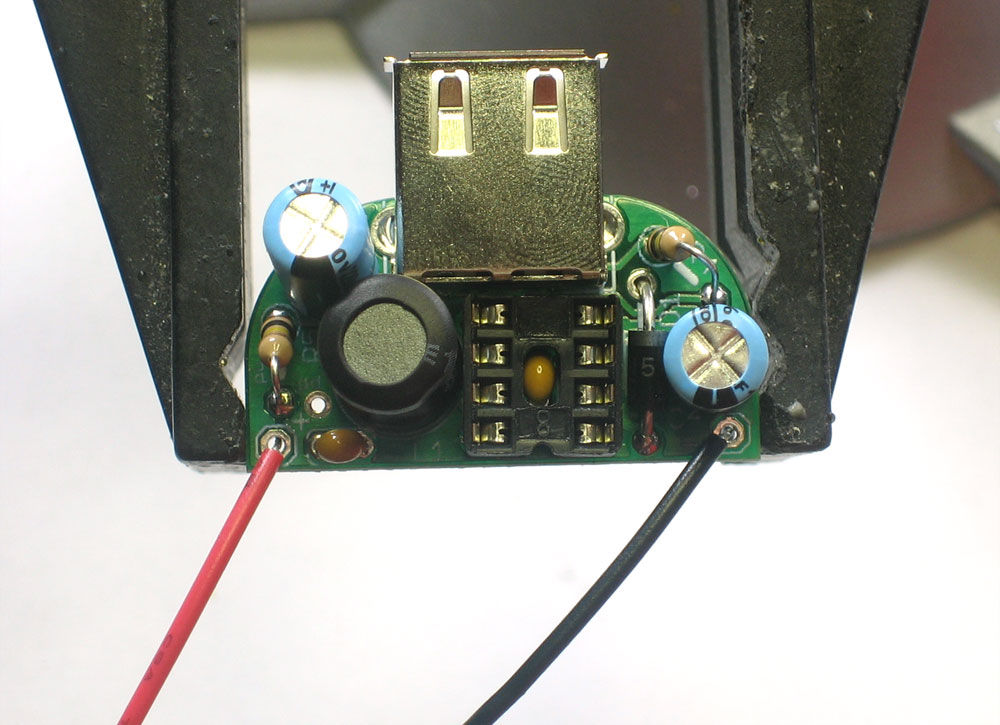
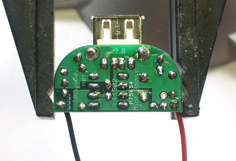
Next, solder in the 2xAA battery holder. The red wire goes to the hole marked + and the black wire goes to the hole marked -. Make sure you have them in right or you can damage the circuit! Solder in the wires, if they're a little long you can clip them. |
 |
Finally, carefully insert the boost converter chip. Make sure the notch in the chip matches the notch in the socket. If the socket was inserted backwards, make sure the notch faces the flat edge of the PCB as shown. Make sure the chip is seated all the way in and that the pins aren't bent. OK! You're done, time to go to the next step which is testing your handywork. |


Mintyboost® is a registered trademark of Adafruit Industries