VCO notes
The VCOs are the heart of the jammer, they generate the ultra high frequencies that we sweep through the RF bands we are jamming. One can build a VCO from raw parts, but its rather painful and I find that if its your first jammer and you dont have a spectrum analyzer, buying is the way to go. I use Minicircuits because they are high quality, wide bandwidth, easy to buy and somewhat low cost. However, Z-Comm, Micronetics and Crystek (available at Mouser) are also possible. If you're going with different VCOs, check the following specifications:
- Vtune: the voltage range required to tune. Wideband VCOs need 15-30V.
- Frequency range: Obviously, you want to make sure you can cover the desired bands.
- Output power: 6dB to 10dB is nice. Above 8dB you'll want to attenuate the output before pushing it thru the gain stage (with the tee network provided onboard).
- Vcc: This board design assumes 12V. Many use 5, 8 or 10V. You can overdrive a little but too much and you'll fry it.
- Case: the pads on the board are for 0.5"x0.5" VCOs, a common size.
The power switches are there to keep power down when using only one VCO at a time. They are not essential and may be jumpered if you know what you are doing. YMMV.
Parts
| Part # & Datasheets | Name |
Description |
Distributor |
Qty |
Cost |
Total |
|---|---|---|---|---|---|---|
VCO1 |
Voltage Controlled Oscillator (1.6-2.5GHz) |
1 |
$22 |
$22 |
||
| ROS-1700W | VCO2 |
Voltage Controlled Oscillator (770MHz-1.7GHz) |
1 |
$25 |
$25 |
|
SS14 (for example) |
D5, D6 |
optional Schottky Diode (at least 1A/20V) | 2 |
$0.30 |
$0.60 |
|
| MIC2506 | IC10 |
7V dual power switch |
1 |
$3.11 |
$3.11 |
|
| MIC2514 | IC11, IC12 |
12V power switch |
2 |
$2.23 |
$4.46 |
|
| 1206 Ferrite bead | L9, L10, |
Noise reducing ferrites | 2 |
$0.12 | $0.24 | |
| 0.1uF 1206 capacitor | C51, C53 |
Bypass capacitors |
2 |
$0.08 | $0.16 | |
| 1.0uF 1206 capacitor | C50, C52 |
Bypass capacitors |
2 |
$0.18 | $0.36 | |
| Total | ~$56 |
Assembly
 |
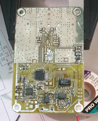
Get ready to solder in the power switches. |
|
Solder in the dual 7V switch (and associated components) as well as the 2 smaller highvoltage switches, one of which is on the other side. |
|
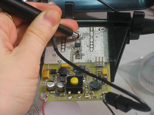
Program the switch test code into the microcontroller and probe (a multimeter is OK too) the output of the switches, they should alternate. |
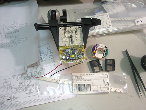 |
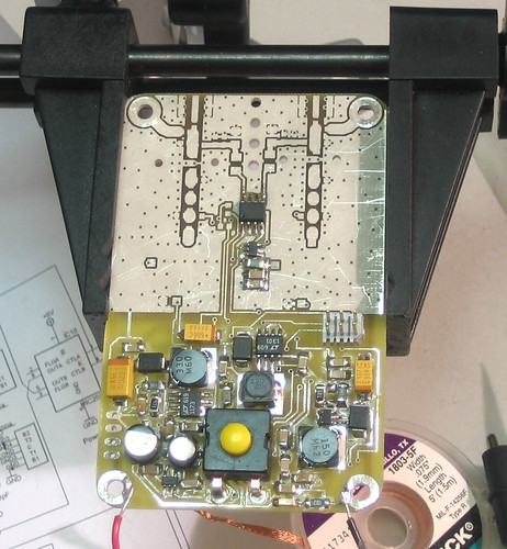
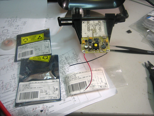
Next are the VCOs |
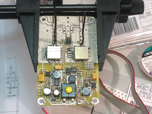 |
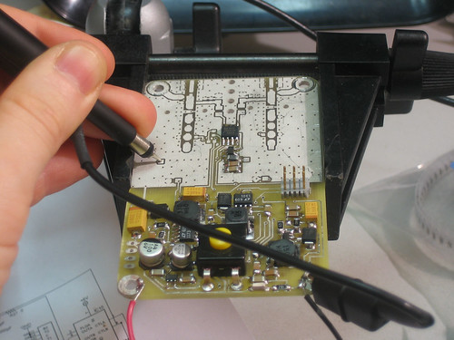
Solder in both VCOs, noting that they are not interchangable. Solder down all the connections: there must be a solid ground plane. Add some simple 1/4 wave wire antennas. |
|
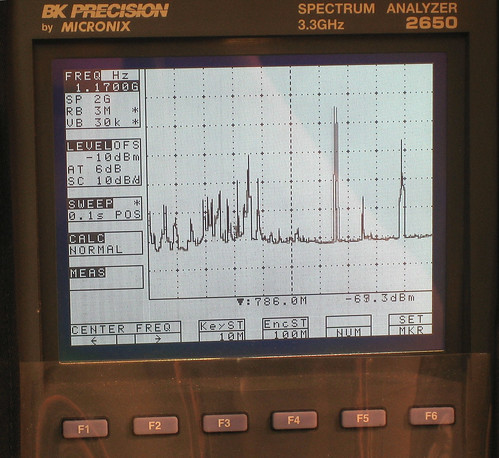
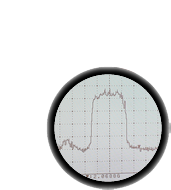
If you have a spectrum analyzer, you can test the VCOs: the test_vco() code will sweep the DC offset, and then sweep the bandwidth. |