The easiest thing to understand is the 3.3V voltage regulator. This takes the 5V supply from the Arduino and converts it to a nice 3.3V supply. This is necessary because SD/MMC cards only work on 3.3V. If you give them 5V they'll burn out & die!
The voltage regulator used is the MCP1700-330, which can provide up to 250 mA of current. There are 4 capacitors associated with the regulator. C1 and C2 are the input capacitors; they stabilize the 5V input. C3 and C4 are the output capacitors, they stabilize the 3.3V output
There is a jumper that allows you to skip the regulator and use the 'built in' 3.3V supply from the Arduino. However, it is not suggested as that supply is not guaranteed to provide the current necessary.
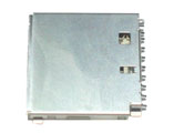
SD/MMC cards are very popular, small, and inexpensive. The card holder is what allows you to remove and replace the card easily. They can be removed/replaced thousands of times. The top three 'pins' are CD, WP and COMMON_SW. CD stands for "card detect" this is a mechanical switch that closes when the card is inserted. WP stands for "write protect", this is a mechanical switch that closes when the card has the little side tab slid down to 'lock'. COMMON_SW is the common connection for the two switches. We simply connect this to ground. Thus CD and WP will be grounded when active
At the bottom are the power supplies. There are 2 mechanical ground connections and a logic ground. There is also the logic power connection, connected to the 3.3v regulator

In the middle are the data connections. DAT1 and DAT2 are for advanced/high-speed SD card interfacing. We don't do this so they are left disconnected. DATA_OUT is the serial data out from the card, which is connected to the SPI port of the Arduino. DATA_IN is the input and SCLK is the clock input. Since they must be 3.3V and the Arduino usually sends 5V data, we use voltage dividers (R2, R3, R4 and R5) to reduce the inputs down.
CS is the select line, used to tell the MMC that we want to send it data. This line is pulled low (to ground) when we want to send data to the card. That means we need to make sure when we dont have anything connected, the pin is pulled high to ~3.3V. We use R6 as the pullup and zener diode D1 to keep the voltage at 3.3V. R1 allows the diode to bias properly when the Arduino pulls the pin high.
The library contains a bunch of specialized code. The first part is a 'FAT16' library, this is a set of functions that allow the chip to read the SD card, locate files and read their contents. The method it does this by is particularly detailed and you can read the SD/MMC and FAT16 manuals if you're interested

Image stolen from Microsoft. Take that, Bill!
Once it opens a file and is ready to read it, it looks through the first section of the file. If it's a Wave file, there will be all sorts of information stored in this header that will indicate the channels (mono/stereo/etc), bits-per-sample (8 to 32), sample rate (ie 16KHz) etc. You can read more about the header format here. Basically, the firmware verifies that it is mono channel, 16 or less bits-per-sample and 22KHz or less sample rate. Then it sets up the audio interrupt that will go off sample-rate times a second. For example, if its a 22KHz audio sample, the interrupt will go off 22,000 times a second!

Image from wikipedia
The audio is encoded in PCM format. This means "pulse Code Modulation". Lets say its a 16bit, 22khz wave. The audio waveform is sliced up 22,000 times a second and a corresponding value (up to 16 bits - from 0 to 65,635) is read from the waveform, then that value is stored in the file. Each sample is a unique value. The file is not compressed. This means the files are very large but the quality is very very good.
The SD card can provide 512 bytes at a time. This is buffered inside the Arduino's RAM so that we have smooth playback. (Techinally, its a double-buffer which means we read 256 bytes and play 256 bytes, then swap.) The audio interrupt picks one sample at a time and sends the data to the DAC (digital/analog converter)
The DAC is a very simple device. When you send it data it will convert that digital information back into an analog signal!

You'll notice it actually doesn't get the orignal waveform perfect. The more bits of digital data, the higher quality of audio reproduction. CDs have 16-bits per sample. While it would have been nice to have a 16-bit DAC, the best option for this design was a 12-bit dac. (That's still quite good.)
The microcontroller/Arduino uses the DAC_CS (chip select), DAC_CLK (data clock), DAC_DI (data), and DAC_LATCH (convert the digital to analog) pins to send the sample data over. The DAC also has a Vref input, this is the reference voltage that it uses to define the maximum analog value it can generate. There is a very low low-pass filter connected to it (C6 and R8) so that any digital noise (there is -a lot-) will not make it into the audio signal.
There is another low-pass filter connected to the output of the DAC (R7 and C8). This is for filtering out the 'square wave' component you see in the recreated-audio wave. Even though the noise is only 1/4096'ths of the signal (about 1.2mV) its still noise and these two components filter out anything above 11KHz. The reason the filter cut-off frequency is 11KHz and not 22KHz is that if you sample at 22KHz you will only be able to reproduce frequencies at half that rate, 11KHz. This is the Nyquist theory. It is sneaky but true. If you try to sample 16KHz waveform at 22KHz it will actually sound much -lower-, it will play at 6KHz (it is 'mirrored' around 11KHz)
Finally there is the volume control and output stage. The potentiometer acts as a simple volume control. It simply divides down the analog signal from 5Vpp down to as low as 0Vpp. The pot is 'audio' type which means that the voltage changes logarithmically, which our ears interpret as linearly.
The analog signal then goes into a high-output, rail-to-rail opamp. This op-amp can provide up to 100mA per channel. The two channels are hooked up in parallel for up to 200mA output (at 5V). This means it can provide 1/8 W into an 8ohm speaker (or 1/4 W into 4ohm speaker). This isn't enough for a boom-box but its good for headphones and small speakers. The output is filtered through a bypass capacitor C9 which will keep any DC voltage from going to the speaker, which could damage it.
The headphone jack is stereo, which both mono channels connected in parallel. This gives the most power output. There are internal switches in the jack so that when the headphones are removed, the audio flows to the 'speaker connection' next to the jack.