Table of Contents
Assembly
The USB boarduino is almost completely assembled. Finishing it up should only take a few minutes
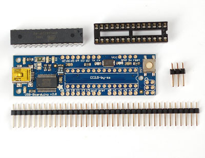
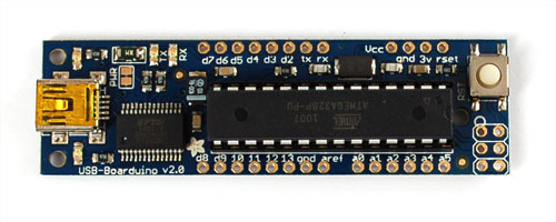
Check the parts in the bag, you should have the tested USB Boarduino board, a stick of 0.1" header, a 2x3 ISP header, a 28pin socket and a preprogrammed ATmega328p
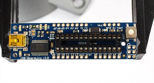
If you want to socket the microcontroller (we suggest it) Place the socket so that the U notch matches the U printed in the silkscreen. If you don't think you'll ever need to replace the microcontroller and you want a slimmer package, skip this stip.
If you have sharp nails you can bend over two of the socket pins to keep them in place
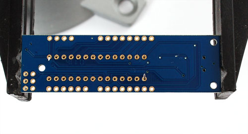
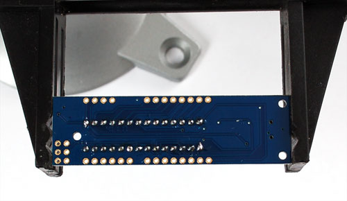
Solder all 28 pins well.
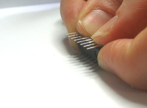
Take the microcontroller out of the foam and carefully bend all the pins so they are straight. We like to grip the chip by the edges and press it against a tabletop.
Once the pins are straight, insert the chip by matching the U notch in the chip with the U notch in the socket
Next, you can attach header pins to make the USB Boarduino fit nicely into a breadboard. If you want to solder wires to the pins instead (free-wiring) you should skip this step.
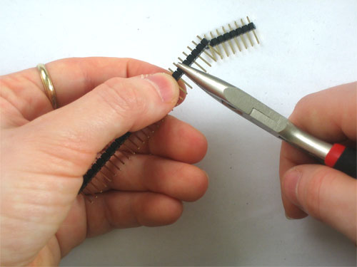
Break the break-away header into four pieces: 4 pin, 6 pin, and two 8 pin
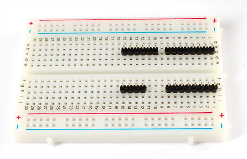
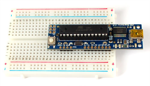
Stick them into any breadboard as shown, they should match up with the USB Boarduino so compare as you place the pieces
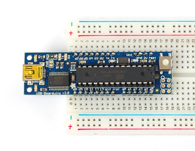
Slip the USB Boarduino on top, it should easily fit
Solder all the pins!
Using with the Arduino IDE
You can use any version of the IDE, when you plug in the USB boarduino it will show up as COM port (install the FTDI drivers that come with the IDE package if you're running Windows or Mac and have not done it yet)
Select Diecimila/Duemilanove with 328P in the Boards menu!
About the design
Here is a brief description of all the elements of the design
Microcontroller
The chip is a ATMega328P which is a standard Arduino-core chip. It comes preprogrammed with a slight modification of the Arduino "Duemilanove" bootloader which takes up 2K. We did not use the bleeding-edge OPTIBOOT as we'd like to wait until its more stable.
The chip is clocked with a 16MHz crystal
Serial Converter
The serial converter is soldered on board, it is a FT232RL. It works great as a USB/serial chip. There are two LEDs connected to it, labeled RX and TX which will blink when data is received or transmitted. A capacitor between the DTR pin and the AVR's Reset pin acts as the auto-reset for reprogramming, which is standard on all classic Arduinos.
Fuse
The USB boarduino has a 500mA fuse between the USB 5V pin and the rest of the board. If you draw over 500mA it will trip (it tends to trip at about 1 Amp)
RESET button
There is a single button that you can press to reset the board, the board has the Arduino bootloader auto-reset capability so you don't need to press this before uploading.
LEDs
There are two LEDs on either side of the USB port. The green one indicates power (its lit if the board has power) and the red one is connected to pin 13 just like classic Arduinos. You can use the pin 13 LED for debugging. It will also blink during bootloading and right before the bootloader starts.
PWR jumper
The PWR solder-jumper is a bonus for advanced users, it allows you to run the USB Boarduino at a different voltage. It is by default shipped with a trace connecting the two jumper sides, which means that the AVR is running at 5V from the USB port. If you would like to say, run the AVR at 3.3v, you can cut the jumper with a sharp xacto/craft blade (check with your multimeter that it is no longer shorted) and then on the breadboard, connect the *VCC* pin to the 3v pin. This will run the board off of the FTDI chip's internal 3.3v regulator, which we should warn you can't supply more than maybe 50mA. Also, be aware that running a 16MHz AVR at 3.3v is considered 'overclocking'. We've never had a problem with it for hobbyist use but just be aware that this is outside the guaranteed performance of the microcontroller
ISP header
If you want to use the chip as a non-Arduino, rather you jutst want it as an AVR devboard, you can reprogram it via the ISP port. We provide a 2x3 pin standard ISP header. Pin 1 is indicated with a circle
Download
All files are at the GitHub repository Click Download to get the files!

