
Fuses are an extremely important part programming a chip, but are rarely explained thoroughly. You only need to set them once, but if you don't do it right, it's a disaster!
Comments? Suggestions? Post to the forum!
You know about flash, eeprom and RAM as parts of the chip. What I did not mention is that there are also 3 bytes of permanent (by permanent I mean that they stick around after power goes out, but that you can change them as many times as you'd like) storage called the fuses. The fuses determine how the chip will act, whether it has a bootloader, what speed and voltage it likes to run at, etc. Note that despite being called 'fuses' they are re-settable and dont have anything to do with protection from overpowering (like the fuses in a home).
The fuses are documented in the datasheets, but the best way to examine the fuses is to look at a fuse calculator such as the avr fuse calculator from the palmavr project
Click on that link in a new window and select ATtiny2313 for the fuse calculations
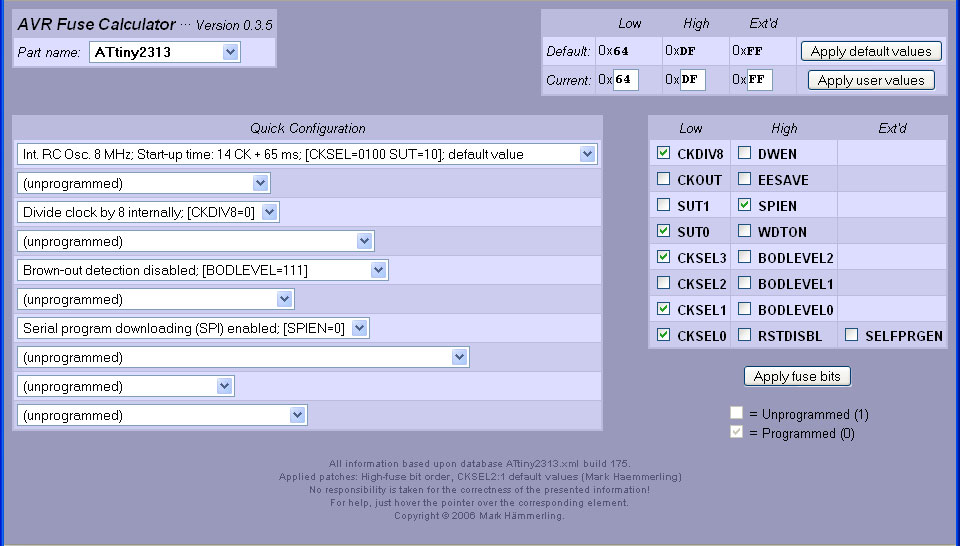
We'll use the Quick Configuration so use those menus, not the checkboxes
The first option is how the chip is clocked. Every CPU uses a clock, The clock keeps track of time for the chip, in general one assembly code instruction is run every clock cycle.The one in your PC has a clock that runs at 1GHz or higher. This little chip runs much slower. If you look at the menu you'll see a huge list of options, but looking carefully you'll see there are two groupings, the Clock Source, the Clock Startup
The Clock Source can be either of the following:
External Clock, Internal 8MHz clock, Internal 4MHz clock, Internal 128KHz clock, External Crystal (0.4-0.9 MHz), External Crystal (0.9MHz - 3.0MHz), External Crystal (3.0MHz - 8.0MHz) or External Crystal (8.0MHz +)
The Clock Startup can be either of the following:
14CK + 0 ms, 14CK + 4 ms, 14CK + 65 ms.
External Clock means that a square wave is being input into the CLOCK-IN pin. This is pretty rare unless you have a clock generating chip. Don't use this unless you're sure you mean to
Internal Clock means that theres a little oscillator inside the chip, its not very precise but good for most projects that dont have fine timing issues. The clock varies with temperature and the power supply voltage. You can chose from a 8MHz, 4MHz or 128KHz clock. The 128KHz clock is for very low power applications where running the chip very slowly helps conserve power. Having an internal oscillator means we don't need to wire up a crystal and we can use the clock pins for our own nefarious purposes.
External Crystal
If you need a special clock rate, like 3.58MHz or 12MHz or a high precision clock that won't drift with the temperature, you'll want an external crystal or oscillator.
Crystals look something like this: Ceramic oscillators look like this:
Crystals come in multiple different pacakges, they may be cylindrical, or larger than the image shown. In both cases the speed is printed on top or on the side, almost always in MHz.
The Startup Time is just how long the clock source needs to calm down from when power is first applied. Always go with the longest setting 14CK + 65ms unless you know for a fact your clock source needs less time and 65ms is too long to wait.
By default, chips that come from the factory have the Internal 8 MHz clock with 14CK + 65ms Startup.
The next option is Clock Out on PortD2 which means, basically, that whatever the clock input is (internal, external, crystal, etc) a square wave of the same frequency will appear on pin D2. This is useful if you're debugging the clock rate, or if you want to use the clock to drive another chip.
By default, chips that come from the factory have this turned off.
This fuse causes the chip to divide the clock rate by 8. So if the clock source is set to Internal 8MHz and you have this fuse set, then you'll really be running at 1MHz.
By default, chips that come from the factory have this turned on.
This fuse turns the Reset pin into a normal pin instead of a special pin. If you turn this fuse on you cant program the chip using ISP anymore. I would suggest you never set this fuse unless you really mean to.
By default, chips that come from the factory have this turned off (that is, Reset is enabled)
These fuses set what voltage to turn the Brownout protection circuitry on. A "brown-out" in this case is the same as when the power-grid gets over-taxed by thousands of people running their air conditioners in the summer: the voltage drops and your clock radio maybe stops working. A brownout for a chip means that the power voltage is too low for it to run reliably at the speed of the clock.
For example, the attiny2313 can run as fast at 20MHz but only if the powervoltage is between 4.5V and 5.5V. If the voltage is lower than that, it may behave erratically, erasing or overwriting the RAM and EEPROM. It may also start running random piece of the flash program. To keep it from doing that, set the brownout voltage to 4.3V, then if the voltage dips, the chip will turn off until the voltage returns. It will then reset and start over.
If the chip is meant to run at 5V, set the brown-out to 4.3V. If the chip can run as low as 3.3V you can set the brown-out to 1.8V. If the chip is a 'low voltage compatible' chip such as the attiny2313V (which can run as low as 1.8V if its clocked at 4MHz or less) then you can set the brownout to 1.8V. You can read the speed and voltage grades on the front page of the datasheet.
By default, chips that come from the factory don't have brown-out detect however I suggest you set it if you can. If you have a bootloader or are storing data in the EEPROM you must set the BOD!