Being able to poke voltages into your projects will help you debug. You can buy an adjustable power supply for $50 or so, or build your own from a kit (another one) Just look for any power supply kit that has a LM317 in it.
You can also build it for $10 using a 9V battery as input and test clips for outputs. This won't be able to provide a lot of power (cause its just a 9V) but it can go pretty far for testing and debugging
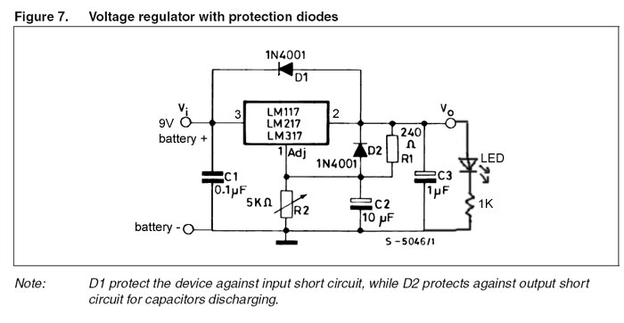
The schematic is adapted from the one on page 9 of the datasheet and, yet, there is a mistake!
Note: in the schematic, pins 3 and 2 are swapped. Follow the directions below if you're confused.
Note that the LM317 is NOT connected to ground at any pin!
| Image | Name |
Description | Part # |
Qty |
Price (approx) |
|||||||
|---|---|---|---|---|---|---|---|---|---|---|---|---|
 |
IC1 |
Adjustable voltage regulator | LM317T |
1 |
$2 |
|||||||
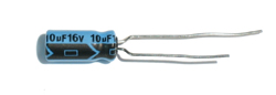 |
C2 C3 |
10uF capacitor (or larger) 10V rating (or larger) | 2 |
$1 |
||||||||
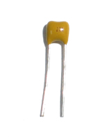 |
C1 |
0.1uF ceramic capacitor | 1 |
$0.50 |
||||||||
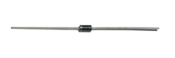 |
D1 D2 |
Protection diode | 1N4001 | 2 |
$1 |
|||||||
|
R1 |
~240 ohm resistor (200 to 270 is fine) ($0.25) | 1 |
$0.25 |
||||||||
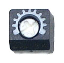 |
R2 |
5K potentiometer. In this case a 1K pot is fine too. I like the thumbwheel ones for this project | 1 |
$1 |
||||||||
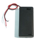 |
9V battery pack with switch |
1 |
$2 |
|||||||||
| 9V battery | 1 |
$2 |
||||||||||
| Breadboard | 1 |
$2 |
||||||||||
| Red LED (optional) | 1 |
$0.50 |
||||||||||
|
1K resistor (optional | 1 |
$0.25 |


|
Make sure you have all the necessary parts |
 |
Solder in the 220 ohm resistor, the 5K potentiometer, the LM317T and the 9V battery pack. Remember that two pins of the 5K potentiometer must be shorted. In this case the left pin and the middle pin are tied together |
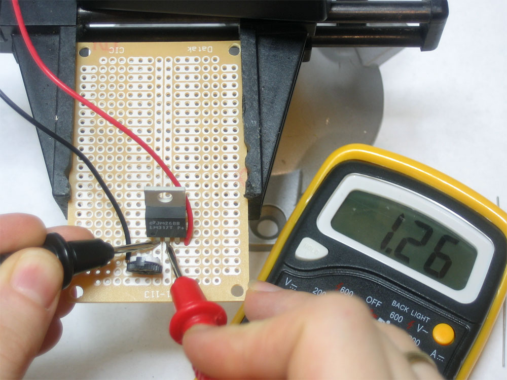 |
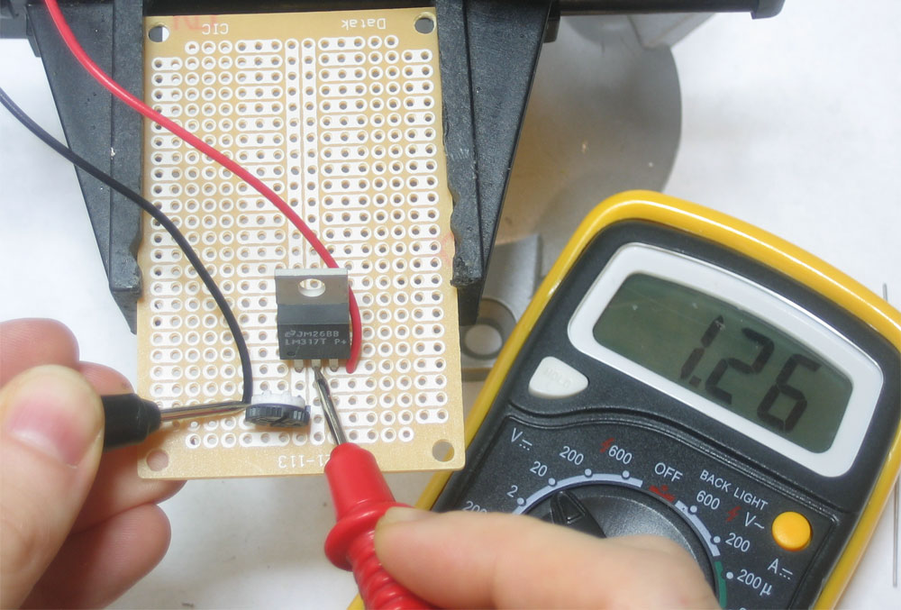
Measure the voltage between the left and middle pin of the LM317. It should be almost exactly 1.25V. If it isn't, check your wiring, are you sure the parts are connected up right and the battery pack is turned on? |
|
Measure between ground (the black wire of the battery pack) and the middle pin of the LM317. By turning the potentiometer you should be able to vary the voltage from about 1.25V to about 7V |
 |
Solder in the remaining parts. Some are hidden in this photo but just follow the schematic and you should be good to go. Perform all the tests so far again |
|
With the red LED connected from the output to ground through the 1K resistor, you can quickly gauge how high the output voltage is. If the output is low the LED will be dim or off. If the output is high, the LED will be bright |
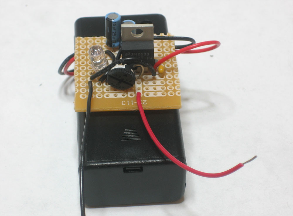 |
Cut the PCB down and glue it to the top of the 9V battery case. Use the red and black wires as output. |