This documentation is for the XPort type modules, not WIZnet! See the Ethernet Shield library for WIZnet documentation.
PLEASE NOTE! We do not manufacture, sell or support Lantronix or WIZnet products! These examples are for your information and entertainment, we do not guarantee they work - many have had changes to the IDE and underlying libraries - and they are offered AS IS
I've written a library to make talking to the XPort devices -really- easy!
Here's the interface:
- Create an AF_XPort object at the top of your sketch, calling it with the pin designations you are going to use. For example:
AF_XPort xport = AF_XPort(XPORT_RXPIN, XPORT_TXPIN, XPORT_RESETPIN, XPORT_DTRPIN, XPORT_RTSPIN, XPORT_CTSPIN)
If you're not using one of those pins, like for example RTS, simply put a 0 instead - In the setup() procedure, initialize the device by calling begin(baudrate)
For example, xport.begin(57600) - You can reset the XPort by calling reset()The procedure will return ERROR_TIMEOUT (the XPort didn't seem to reset) or ERROR_BADRESP (the XPort didn't reset properly, perhaps) or ERROR_NONE (good)
- Connect to an IP address and port with the procedure connect(ipaddr, port ), where ipaddr is in dotted decimal format like "127.0.0.1" and port is simply a number. The procedure will retrun ERROR_TIMEDOUT (the XPort didnt respond), ERROR_BADPRESP (failed to connect), or ERROR_NONE (connected)
- Once you're connected you can check to see if data is available with serialavail_timeout(timeout) which will spend up to timeout milliseconds waiting for data. It returns 1 if data is available, and 0 if not.
- You can read data one line at a time by calling readline_timeout(buffer, maxlen, timeout) which will read one full line of text/data (everything up to a new line) until either timeout milliseconds have gone by without more data or maxlen number of characters have been read. buffer is a character array that is used to store the line of text. Check out the examples below for detailed usage.
- You can also write data by calling print() or println() just like the Serial library. Since you may have data that's just lots of strings (like javascript code, or HTML or whatever) that don't change, you can use ROM_print(string) which will read from PROGMEM arrays. See the webserver examples for how to use this. In general, you can store as much data in flash as you'd like, but by default strings are stored in RAM which quickly gets exhausted.
- When you're done, you can call flush() which will empty out all of the data waiting on the XPort
Here are some example sketches using the NewSoftSerial library and AF_XPort library to talk to the XPort. You'll notice that most use the same chunk of XPort interfacing code and then just send data and look for responses. These examples should get you going in the right direction...
These examples all use a local (Ardino USB) baudrate of 57600 and an xport baudrate of 57600. They probably wont work without wiring up the xport RESET, DTR, CTS pins (RTS is indicated but isnt actually used), the xport Channel 1 flow control should be "02"
*** Channel 1
Baudrate 57600, I/F Mode 4C, Flow 02
Port 10001
Connect Mode : D4
Send '+++' in Modem Mode enabled
Show IP addr after 'RING' enabled
Auto increment source port disabled
Remote IP Adr: --- none ---, Port 00000
Disconn Mode : 00
Flush Mode : 77
Here is an example webserver with javascript. The XPort is open on port 80 (standard http port) and will present a webpage:

On the page is a color-picking javascript object. The box with #xxxxxx in it indicates the current color of the LED (red, green, blue hex) and an approximate color representation. You can change the color by clicking on the "..." button

which will pop up the color picking table. Select the color desired...
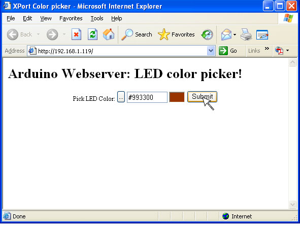
And then click Submit to update the LED on the arduino!
On the hardware side, I used a single RGB (tri-color) LED, common-anode type with the three LEDs connected to pins 9, 10 and 11. The XPort's RX and TX are connected to pins 2 and 3. You can watch debug output on the Serial monitor (ie each time a connection is made)

The XPort is configured thusly:
*** Channel 1
Baudrate 57600, I/F Mode 4C, Flow 00
Port 00080
Connect Mode : D4
Send '+++' in Modem Mode enabled
Show IP addr after 'RING' enabled
Auto increment source port disabled
Remote IP Adr: --- none ---, Port 00000
Disconn Mode : 80 Disconn Time: 00:03
Flush Mode : 77
Note the different port and Disconn Time settings. If you're using a Direct+ or a normal XPort you can avoid using the disconnect timeout to drop connections but I couldnt get it working on the Direct. This works just fine tho.
Memory used is ~12K flash (a lot of that is the javascript code for the color picker) and maybe 512 bytes of RAM.