Table of Contents
Introduction
LCDs are a fun and easy way to have your microcontroller project talk back to you. Character LCDs are common, and easy to get, available in tons of colors and sizes. We've written tutorials on using character LCDs with an Arduino (or similar microcontroller) but find that the number of pins necessary to control the LCD can be restrictive, especially with ambitious projects. We wanted to make a 'backpack' (add-on circuit) that would reduce the number of pins without a lot of expense.
By using simple i2c and SPI input/output expanders we have reduced the number of pins (only 2 pins are needed for i2c) while still making it easy to interface with the LCD. For Arduino users, we provide a easy-to-use library that is backwards compatible with projects using the '6 pin' wiring.
For advanced users, this project can be used for general purpose I/O expansion, the MCP23008 has 8 i/o pins (7 are connected) with optional pullups, the SPI 74HC595 has 7 outputs.
Assembled and tested backpacks are available for purchase for only $10 in the Adafruit shop!
Which LCD to use
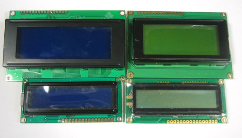
This backpack will work with any 'standard'/'classic' character LCD. It does not work with graphic LCDs. Character LCDs come in sizes ranging from 8x1 (8 characters, one line) to 40x4 (40 characters, four lines). The backpack will also only fit LCDs that have a single line of pins at the top, not the ones that have a 2x10 or 2x8 connector on the side. Those are much rarer these days but just keep a look out for that!
Assembly
Putting together the backpack onto an LCD is a quick process, and should take only a few minutes with a soldering iron.
Parts check
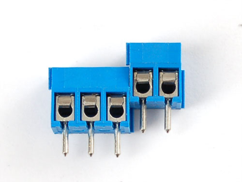
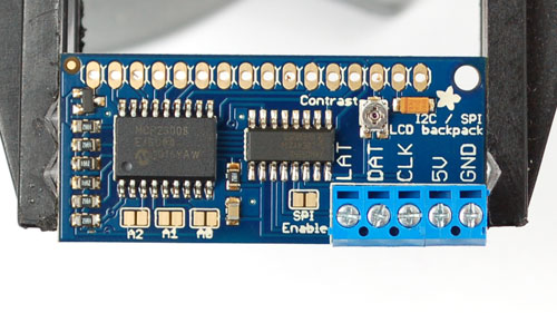
Verify you have everything in the bag, there should be an assembled and tested PCB, a 2-pin and 3-pin 3.5mm terminal block. The backpack does not come with header or an LCD.
Terminal blocks
The terminal blocks allow you to easily attach and remove the LCD from your wiring, which we think is awfully handy. If you dont want the terminal blocks (they stick out a bit) you can always skip this step.
The terminal blocks come in 2 and 3-pin pieces. Slide them together.
Place the blocks over the corner area of the backpack so that the holes stick out (unless for some reason you want them to face the other way)
Solder them into place
Prepare LCD
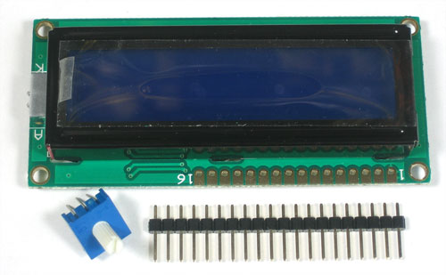
Next we will attach the backpack to the LCD. First we must put header onto the LCD, if you bought the LCD from us, it will come with a stick of header. Otherwise, pick up some standard 0.1" male header
These photos shows a 10K potentiometer, you can ignore it
If the header is too long, just cut/snap it short so that it is 16 pins
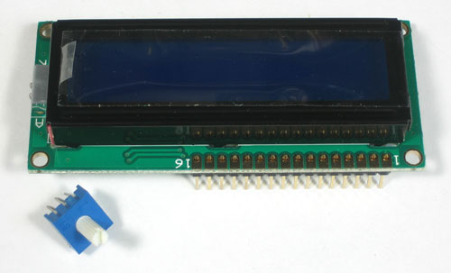
Next you'll need to solder the header to the LCD.You must do this, it is not OK to just try to 'press fit' the LCD!
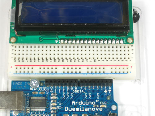
The easiest way we know of doing this is sticking the header into a breadboard and then sitting the LCD on top while soldering. this keeps it steady.
Attach LCD
Now we will attach the backpack. We will show how to do this in a permanent fashion. If you think you would like to remove and replace the LCD at some time, you can use a piece of 16-pin long 0.1" female header as a socket but be aware it will stick out a lot.
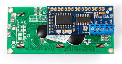
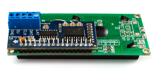
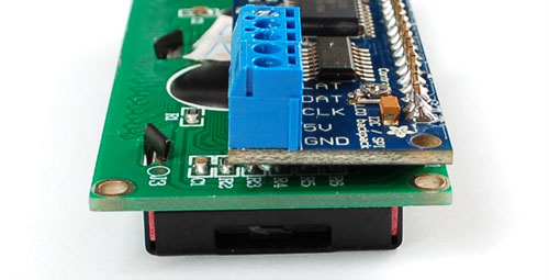
There are two options, you can tuck the backpack behind the LCD
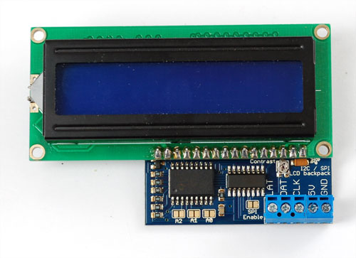
Or solder it so it's to the side, this way it's thinner.
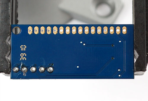
Solder the header to the backpack
Make sure that as you solder the first pin, the backpack PCB isn't leaning against the LCD, where the terminal blocks could short against some components. You can put some electrical tape or foam tape behind to avoid this if you think it could be an issue
That's it!
Connect with I2C
The first option we'll show is how to use the i2c interface on the backpack. We'll be showing how to connect with an Arduino, for other microcontrollers please see our MCP23008 library code for the commands to send to the i2c i/o expander. I2c is nice because it only uses two pins, and you can put multiple i2c devices on the same two pins. So for example, you could have up to 7 LCD backpacks+LCDs all on two pins! The bad news is that you have to use the 'hardware' i2c pins that are only on Analog 4 & 5. You can't change those pins and you can't use them for reading analog data. If you absolutely need those two pins, use SPI (see below)
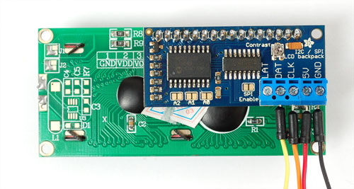
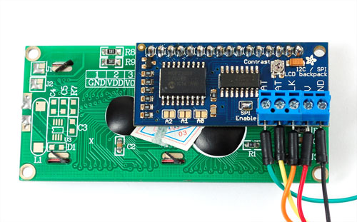
For this we'll need to connnect four wires: GND, 5V, CLK (clock) and DAT (data).
Connect the CLK pin to Analog 5 (i2c SCL pin) and DAT to Analog 4 (i2c SDA pin). Connect the 5V and ground pins to respective power pins.
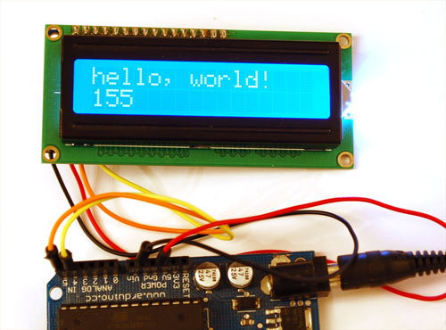
Download and install the new LiquidCrystal library (scroll to the bottom of the page for download links and instructions) Load up the HelloWorld_i2c example sketch in the new LiquidCrystal library. If you don't see the HelloWorld_i2c example go through the process of installing the new library again, make sure you quit and restart. Upload the sketch. You should see the backlight turn on when the Arduino resets. If you don't see any characters, adjust the Contrast trim potentiometer with a mini-screwdriver until you see the text clearly
If you want to have more than one MCP23008 device (like more than one backpack+LCD) each one needs to have a unique 'address'. You can set the address by jumpering the A0 A1 and A2 solder jumpers. By default, no jumpers are soldered, giving an address of 0. If you want to have an address of 3 you would solder A0 (bit 0) and A1 (bit 1) for an address of "011" = 3 in binary. Then in the code change
// Connect via i2c, default address #0 (A0-A2 not jumpered)
LiquidCrystal lcd(0);
to
// Connect via i2c, address #3 (A0&A1 jumpered)
LiquidCrystal lcd(3);
Connect with SPI
Another option for connecting is to use SPI, which is a simpler protocol. The good news about SPI is that its very simple and you can use any 3 pins to connect. You can share the data and clock pins with another device as long as they remain outputs, the latch pin should only be used for the backpack. So if you wanted 3 LCDs, for example, they would all have the same data and clock pins, but the latch pin would be different, for 5 pins total.
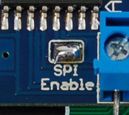
The first thing you will need to do is to enable SPI. To do this, solder the SPI Enable solder jumper by heating up the pads with a soldering iron and soldering a blob onto both pins
This will switch the backpack over to SPI mode instead of i2c. If you want to go back to i2c, use wick or a solder sucker to remove the jumper
Next we will connect 5 wires, 5V, GND, DAT, CLK, and LAT. To match the example, CLK goes to to Digital 2, DAT to Digital 3, and LAT to Digital 4. Once we have the example sketch running you can of course change these to anything you'd like. Connect 5V and GND to the 5v and Ground Arduino power pins
Download and install the new LiquidCrystal library (scroll to the bottom of the page for download links and instructions) Load up the HelloWorld_SPI example sketch in the new LiquidCrystal library. If you don't see the HelloWorld_SPI example go through the process of installing the new library again, make sure you quit and restart. Upload the sketch. You should see the backlight turn on when the Arduino resets. If you don't see any characters, adjust the Contrast trim potentiometer with a mini-screwdriver until you see the text clearly
Download
Arduino Library
We made a modification to the LiquidCrystal library so you can use it for i2c, spi or straight-up-6-pin connections. You can get the modified library that supports SPI/i2c from GitHub.
To download and install it:
- Click the Downloads button in the top right of the GitHub page
- You will need to remove the old library, find the folder ArduinoIDE/libraries/LiquidCrystal and put it somewhere else for safekeeping.
- Uncompress the downloaded library, the folder will be called something like adafruit-LiquidCrystal-xxxxx. Look inside and verify you see a file called MCP23008.h. Rename the folder LiquidCrystal and drag it into your personal library folder which is in arduinosketchfolder/libraries
- Quit and restart the Arduino IDE
If you have a hankering to use the backpack as a general purpose i2c expander, you should use the plain MCP23008 library, also at github. Its for more advanced users, by the way.
Optimized i2c library
FalconFour posted up a ultra-optimized high-speed i2c library, check it out for better performance!

