Table of Contents
Introduction
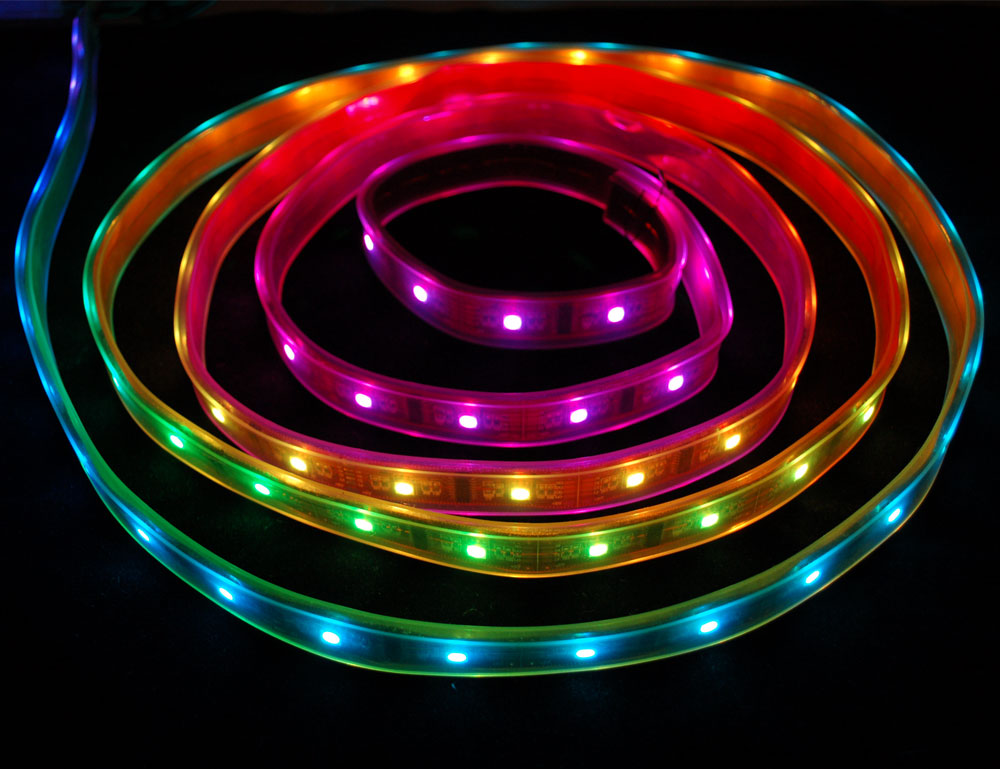
We love some good LED blinking as much as the next person but after years of LED-soldering we need something cooler to get us excited. Sure there are RGB LEDs and those are fun too but what comes after that? Well, we have the answer: Digital LED Strips! These are flexible circuit boards with full color LEDs soldered on. They take a lot of LED-wiring-drudgery out of decorating a room, car, bicycle, costume, etc. The ones we carry come with a removable waterproof casing.
There are two basic kinds of LED strips, the "analog" kind and "digital" kind. Analog-type strips have all the LEDs connected in parallel and so it acts like one huge tri-color LED; you can set the entire strip to any color you want, but you can't control the individual LED's colors. They are very very easy to use and fairly inexpensive.
The Digital-type strips work in a different way. They have a chip for each LED, to use the strip you have to send digitally coded data to the chips. However, this means you can control each LED individually! Because of the extra complexity of the chip, they are more expensive.
You can buy waterproof digital RGB LED strips by the meter at the Adafruit shop!
"Digital" LED strips
This tutorial is for the Digital RGB LED strips only! See the 'analog' RGB strip product page for tutorials on that kind
Technical specs:
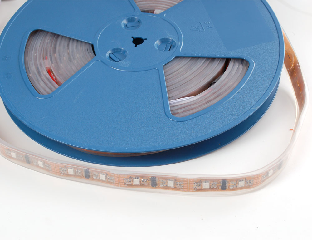
We used to carry the HL1606-chip-based LED strips and now carry the superior LPD8806-type. They look very very similar but have a few differences, in the following specifications the width is different:
- 19mm (0.75") wide (HL1606) or 16.5mm (0.65") wide (LPD8806), 4.5mm (0.18") thick with casing on, 62.5mm (2.45") long per segment
- 32 LEDs per meter (16 segments)
- Removable IP65 waterproof casing
- Maximum 5V @ 120mA draw per 2.5" strip segment (all LEDs on full brightness) - about 2A per meter
- 2 common-anode RGB LEDs per segment, individually controllable
- LED wavelengths: 630nm/530nm/475nm
- Microcontroller required to control strip
Project Ideas

Schematic
The strip is made up of 2.5" segments. Each segment is independent and so you can cut the strip down on the segment boundaries, or extend them, or split them up, etc.
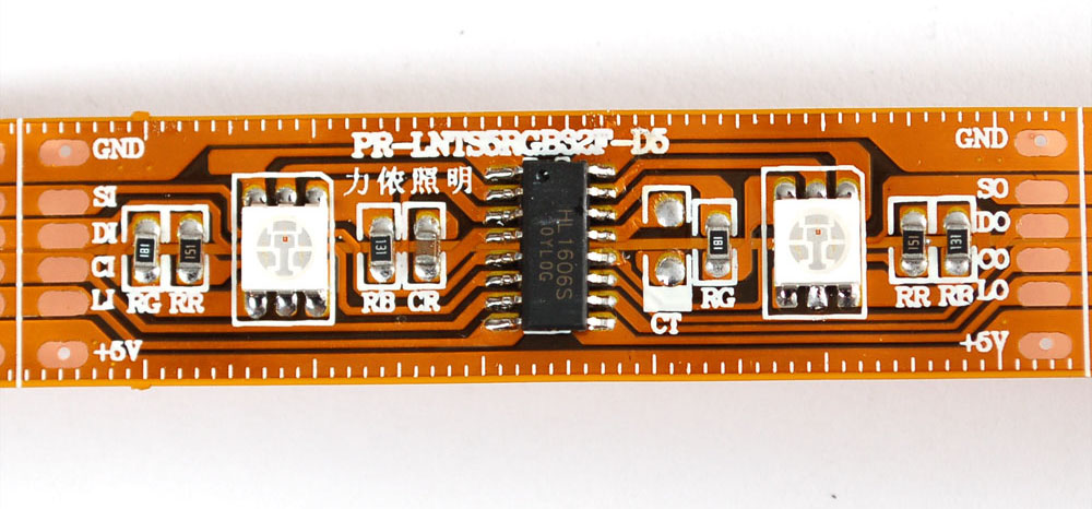
This is what the HL1606-based strip segments look like:
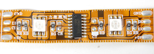
the LPD8806-based strip looks like this (its thinner, and has fewer 'pads' on the side)
Each segment basically acts like this
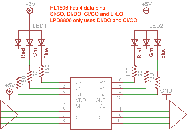
There is one chip (either HL1606 or LPD8806) latch chip, it controls 6 LEDs (2 x RGB) with 2 or 4 input data lines and 2 or 4 output data lines. The HL1606 uses 4 pins, the LPD8806 uses only 2. For both, data is sent on the DI(data in) pin and CI (clock in) pin. The HL1606 also uses the LI (latch in) pin to 'push' the data down the line to the next chip through the DO (data out), CO and LO pins. The LPD8806 has a slightly smarter method by which you send special data to let it know its time to latch. By alternating data sends and latching, you can write to near infinite number of LEDs in the strand - limited pretty much by the power supply!
The SI pin is used by the HL1606 to 'strobe' the built in fading function. We've had difficulty getting it to work reliably in a way that doesn't suck so we wont be using it in the tutorial.
The whole thing is run off of 5V, and data signal should be 5V (although we suppose you can try 3.3V data signals, it might work)
Current draw
Each segment has 6 LEDs total (two red, two green and two blue). Each LED draws about 20mA when lit at full brightness. So if you have the segment set to full white, that will be 120mA from a 5V supply.
Each meter has 16 segments, 32 LEDs so we multiply 16 * 120mA to get the maximum current. Per meter, this comes out to 1.92 Amps. Since the chips also draw a little power, we will round this up to 2A per meter!
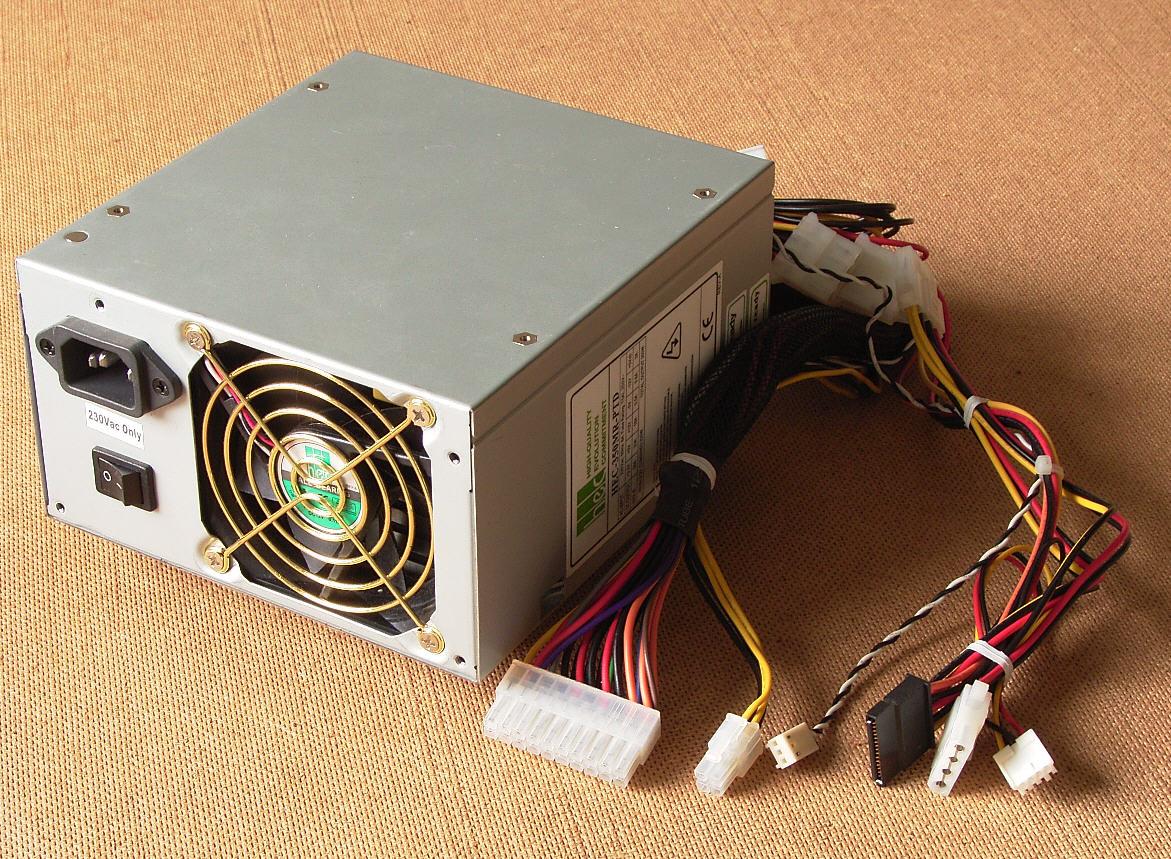
For this reason we suggest getting a large power supply. You can use an ATX power supply (available at every computer or electronics store, really!) and connect the PWR_ON green wire on the large ATX plug (leftmost in the image above) to ground (black) to activate it. Then grab 5V and ground from one of the 4-pin hard drive connectors.
In reality, this is an upper limit. If your project doesn't light up all the LEDs, and uses colors instead of just bright white, the power usage will be a quarter or half. Either way, you'll want to keep this in mind, the power usage adds up and overdrawing from a small power adapter can damage it permanently
Which type of strip do I have?
As we mentioned, there are two strips you may have. If you ordered before August 2011 its going to be the HL1606 type, otherwise you probably have the LPD8806 type. Its not too hard to tell the difference. Look at the segments of the strip and find the 'pads' on the side of each 2.5" segment. The HL1606 strips have 6 pads on each side. the LPD8806 have 4 pads on each side:
This is what the HL1606-based strip segments look like:
the LPD8806-based strip looks like this (its thinner, and has fewer 'pads' on the side)
Wiring the LPD8806 based strips
This wiring tutorial is for the LPD8806 only - its a little bit different than the HL1606 so if the photos don't match up, check which kind you have! If you have a HL1606 strip, click here to read that tutorial!
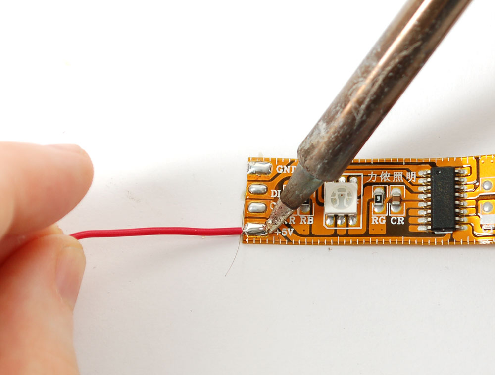
The toughest part of the project is probably just soldering to the strip, its very easy to use! First, cut the piece to the length you want, on the cuttable boundaries. Next, tin the 4 INPUT pins (make sure you're connecting to 5V/CI/DI/GND which is input, not the corresponding 5V/CO/DO/GND pins!). To make the images clearer, we removed the plastic covering for this tutorial. However, you can just cut a little bit away on yours to allow you to access the pads. Once you take off the plastic cover its a bit difficult to get it back on
JUST BECAUSE YOU HAVE A STRIP WITH WIRES SOLDERED ON DOES NOT MEAN THEY ARE ON THE RIGHT SIDE, THEY COULD BE ON THE OUTPUT PINS. CHECK THREE TIMES TO MAKE SURE YOU ARE CONNECTING TO THE INPUT SIDE!
Tin the pads by carefully melting a little solder onto the pads
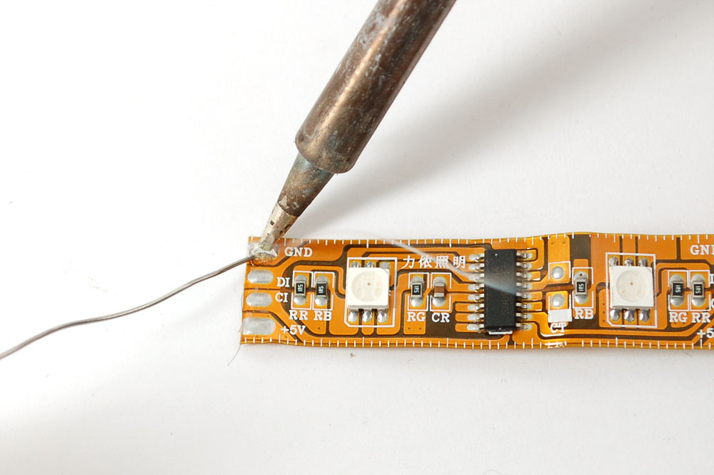
Start by soldering a red wire to the +5V power line
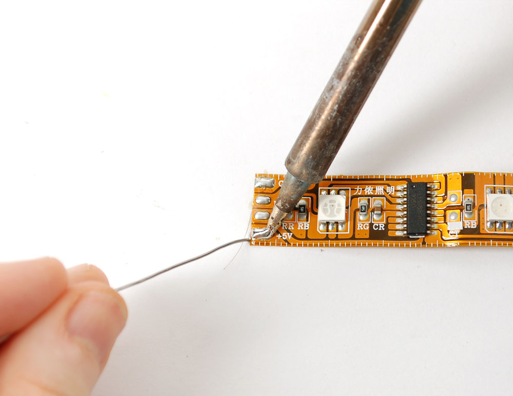
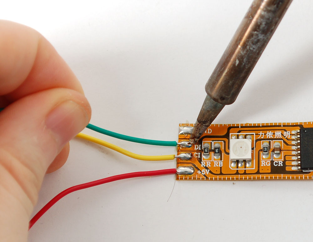
Next connect two wires to the data and clock pads. We'll use yellow for the Clock pin (CI) and green for the data pin (DI)
Finally, solder a black wire to ground
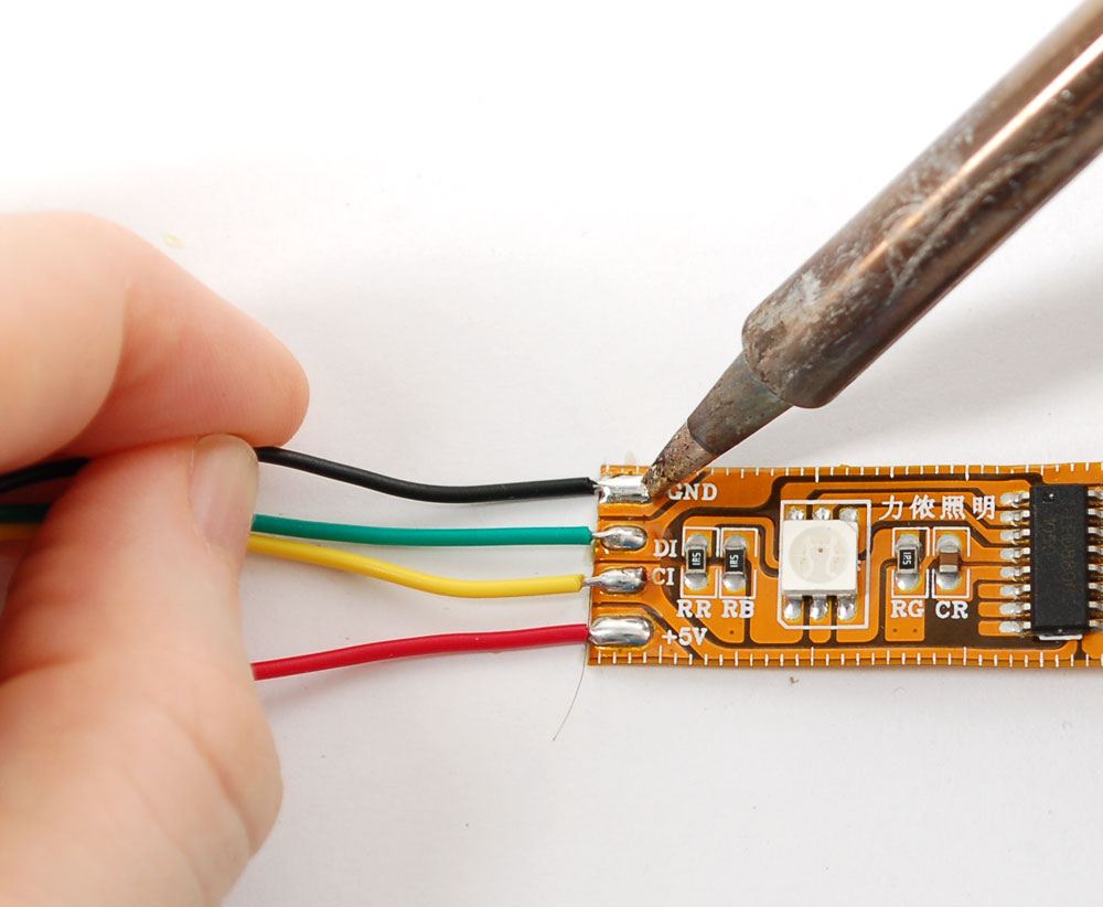
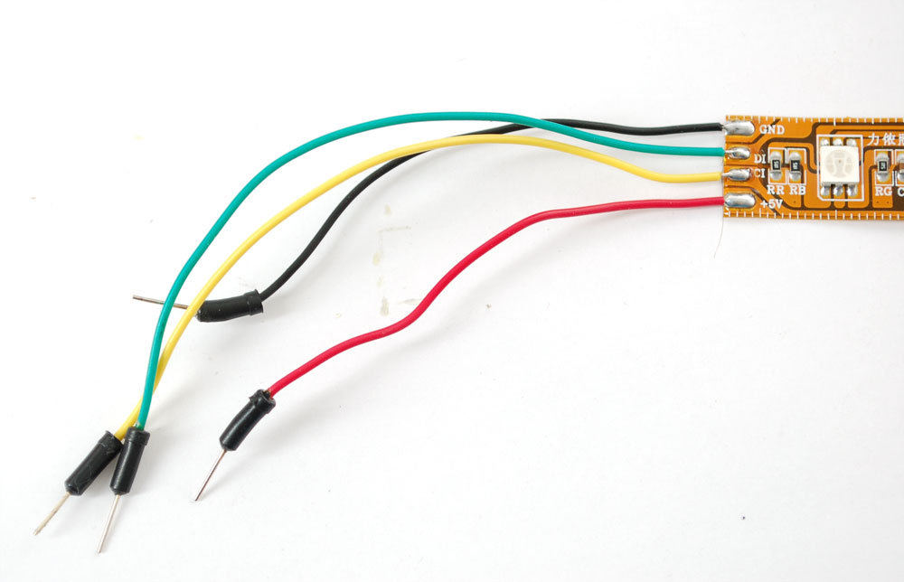
That's it! Now you're ready to use the strip. You may want to use heatshrink to provide a secure cover for the wires, or stuff hotglue in the end, which will do the same.
Using the LPD8806 based strips
The LPD8806-based strips are easier to use than the HL1606, with fewer pins and only one library so this section will be nice and short!
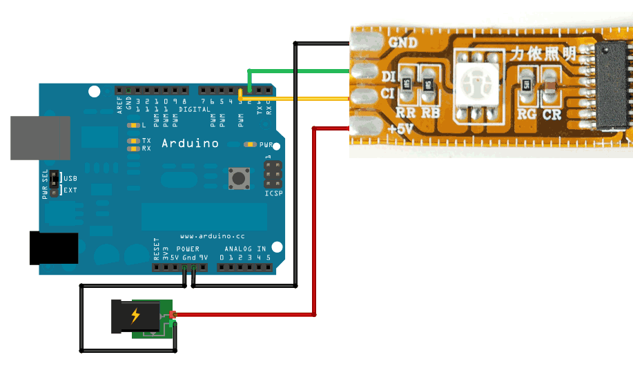
First, connect the strip up to your microcontroller (we'll be using an Arduino)
- Connect the Black Ground to the ground pin of the microcontroller (this is for data and power ground)
- Connect the Yellow Clock wire to digital Pin 3 (you can change this later)
- Connect the Green Data wire to digital Pin 2 (you can change this later)
- Connect the Red +5V power wire to your 5V power supply.
You will need a lot of power for these strips so be sure to read the documentation above to specify a proper supply. Don't just connect it to the Arduino +5V pin and cross your fingers, you could damage your power adapter!
The digital RGB LED strips must be powered with a 5V DC power supply. Do not use anything higher than 6VDC or you could permanently destroy the entire strip!
Next you'll need to install the LPD8806 library code. Download the library from github by clicking the DOWNLOADS button in the top right corner, rename the uncompressed folder LPD8806. Check that the LPD8806 folder contains LPD8806.cpp and LPD8806.h
Place the LPD8806 library folder your <arduinosketchfolder>/libraries/ folder. You may need to create the libraries subfolder if its your first library. Restart the IDE.
Load up the File→Examples→LPD8806→StrandTest sketch, you might want to change the line that says
LPD8806 strip = LPD8806(32, dataPin, clockPin);
so that the first argument to the object is the number of LEDs in your strip. Each meter has 32 LEDs so count them or do the math. Now upload it to your Arduino, your strip should start to perform a bunch of demonstration tests!
Netduino and the LPD8806 based strips
Driving these strips from Netduino (or other .Net Micro Framwork boards like FEZ Panda) is very convenient and doesn't require a code library if SPI ports are used. The following sample shows driving a 32 pixel light strip connected to SPI1 (SCLK on pin 13 and MOSI on pin 11):
using Microsoft.SPOT.Hardware;
...
        public static void LightStripSpi()
        {
            var spi = new SPI(new SPI.Configuration(Cpu.Pin.GPIO_NONE,
                false, 0, 0, false, true, 10000, SPI.SPI_module.SPI1));
            var colors = new byte[3 * 32];
            var zeros = new byte[3 * ((32 + 63) / 64)];

            while (true)
            {
                // all pixels off
                for (int i = 0; i < colors.Length; ++i) colors[i] = (byte)(0x80 | 0);
                // a progressive yellow/red blend
                for (byte i = 0; i < 32; ++i)
                {
                    colors[i * 3 + 1] = 0x80 | 32;
                    colors[i * 3 + 0] = (byte)(0x80 | (32 - i));
                    spi.Write(colors);
                    spi.Write(zeros);
                    Thread.Sleep(1000 / 32); // march at 32 pixels per second
                }
            }
        }
FAQ & Troubleshooting
99% of Digital LED strip problems come down to a few very common problems. BEFORE posting, check all of these multiple times.
- You are connecting to the INPUT of the strip, not the OUTPUT. This is incredibly common mistake. It wont work unless data is going into the correct end. Check the tutorial to see how to identify the input side. Just because your cut strip has a connector does NOT mean its an input. Check again!
- You must have a common ground between your power supply and the Arduino. If no ground wire connects the strip to the Arduino, it will be flakey and respond strangely, if at all
- If you want to light up a lot of LEDs, you need a fairly beefy 5V supply. Make sure its a regulated supply, and you verify that the output is no higher than 6V DC. A good rule of thumb is a max of 2 Amps per meter, with an average draw of about 0.5 - 1 amp depending on use.
- Check that you did not swap the DATA and CLOCK pins
For long strips, there can be a significant drop in voltage from one end to the other. For strips longer than 1 meter we recommend feeding power to both ends of the strip. For very long strips (5 meters or more) you should plan to feed power to multiple points along the strip.
Mysterious Green Flash- On some strips it has been reported that the first pixel on the strip will flash a little green whenever commands are sent to this strip (If you are sending commands continuously, it might show some green most of the time). We are still trying to understand the cause of this phenomenon. In any case, it does not otherwise affect normal operation of the strip.
How to separate longer strips (Advanced!)
This mini-tutorial is a little on the advanced side, its going to show how to separate the LED strips on the overlapping section ends. All the strips are made of 1/2meter long sections. Between every 2 LEDs you can cut off the flex PCB at the dotted lines. However, every 1/2 meter you cannot just cut the strip but must pull apart the soldered sections. Its not terribly hard but worth documenting!
For this, we use the wide flat tip on our METCAL iron. A wide tip isnt required but it sure is handy!

Using an x-acto knife, cut two slice from the top on either side of the solder connection


Then slice the rubber coating between the two cuts you made


Pull off the thin rubber piece between the cuts

Press the soldering iron against the four joints while pulling the two pieces apart


Cut the remaining rubber underneath with scissors

Thats it!

