Table of Contents
We love our black and white monochrome displays but we also like to dabble with some color now and then. Our new 0.96" color OLED displays are perfect when you need an ultra-small display with vivid, high-contrast 16-bit color. The visible portion of the OLED measures 0.96" diagonal and contains 96x64 RGB pixels, each one made of red, green and blue OLEDs. Each pixel can be set with 16-bits of resolution for a large range of colors. Because the display uses OLEDs, there is no backlight, and the contrast is very high (black is really black). We picked this display for its excellent color, this is the nicest mini OLED we could find!
This OLED uses the SSD1331 driver chip, which manages the display. You can talk to the driver chip using either 3 or 4-wire write-only SPI (clock, data, chip select, data/command and an optional reset pin) or standard 8-bit parallel 8080/6800 which also permits reading pixel data from the display. Our example code shows how to use SPI since for such a display, its plenty fast. Inlcuded on the fully assembled breakout is the OLED display and a small boost converter (required for providing 12V to the OLED) and a microSD card holder. Our example code shows how to read a bitmap from the uSD card and display it all via SPI.
The logic levels for the microSD ard and OLED are 3.3V max. In order to make this breakout usable for bidirectional 8-bit and SPI interfaces, we left out an on-board level shifter. However, we include a DIP chip 75LVC245 8-bit level converter chip and our tutorial shows how to wire it to an Arduino so that you can use the breakout with 5V logic such as that of an Arduino. If you have a 3.3V logic level microcontroller system, you can skip the level shifter.
Of course, we wouldn't just leave you with a datasheet and a "good luck!" - we've written a full open source graphics library that can draw pixels, lines, rectangles, circles, text and bitmaps as well as example code and a wiring tutorial. The code is written for Arduino but can be easily ported to your favorite microcontroller!
Power
OLEDs tend to be fairly low power since they don't have a backlight, but they do require high voltage to drive the OLED segments. For this reason there is a boost converter on the back of the OLED. There's also a 3.3V regulator. However, we've found that it can be very sensitive to noisy 5V supplies such as that on an Arduino so try to run it off the 3.3V line which is filtered and cleaner. The power usage will vary with how many pixels are lit, the maximum is around 25mA.
Of course, the microSD card is another matter - and may draw up to 150mA or more during writes (check the OEM document for the card to understand current usage!)
Wiring
The OLED module supports 3 methods of communication: 4 wire SPI, 8-bit parallel in 8080 and 6800 format. Since the display is small and we like to save pins, we'll be using the SPI protocol. Our tutorial, wiring and example code is all for SPI so if you need 8-bit, check the datasheets for details on how to wire up for 8-bit parallel.
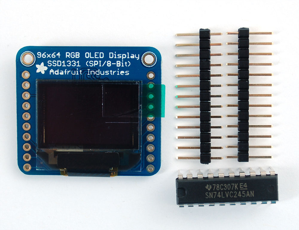
Since the OLED is 3.3V and also uses 3.3V logic, we need to use a logic shifter. We include a DIP logic shifter, the 74LVX245 with the OLED. If you're using a 3.3V logic chip, you can skip the logic analyzer. Arduinos are all 5.0V so we'll be demonstrating that
Don't forget to solder a piece of 0.1" header onto the left side of the OLED so you can plug it into a breadboard. You cannot skip this step, the header MUST be soldered in before plugging it in and wiring it up or it won't work!
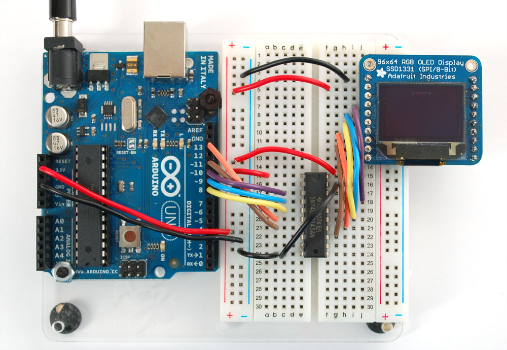
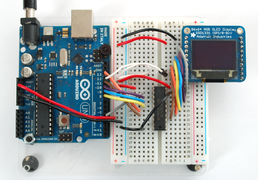
Plug in the OLED and the '245 chip. The Chip has the notch closest to the OLED. Click on the image to see a large photo if you need help orienting
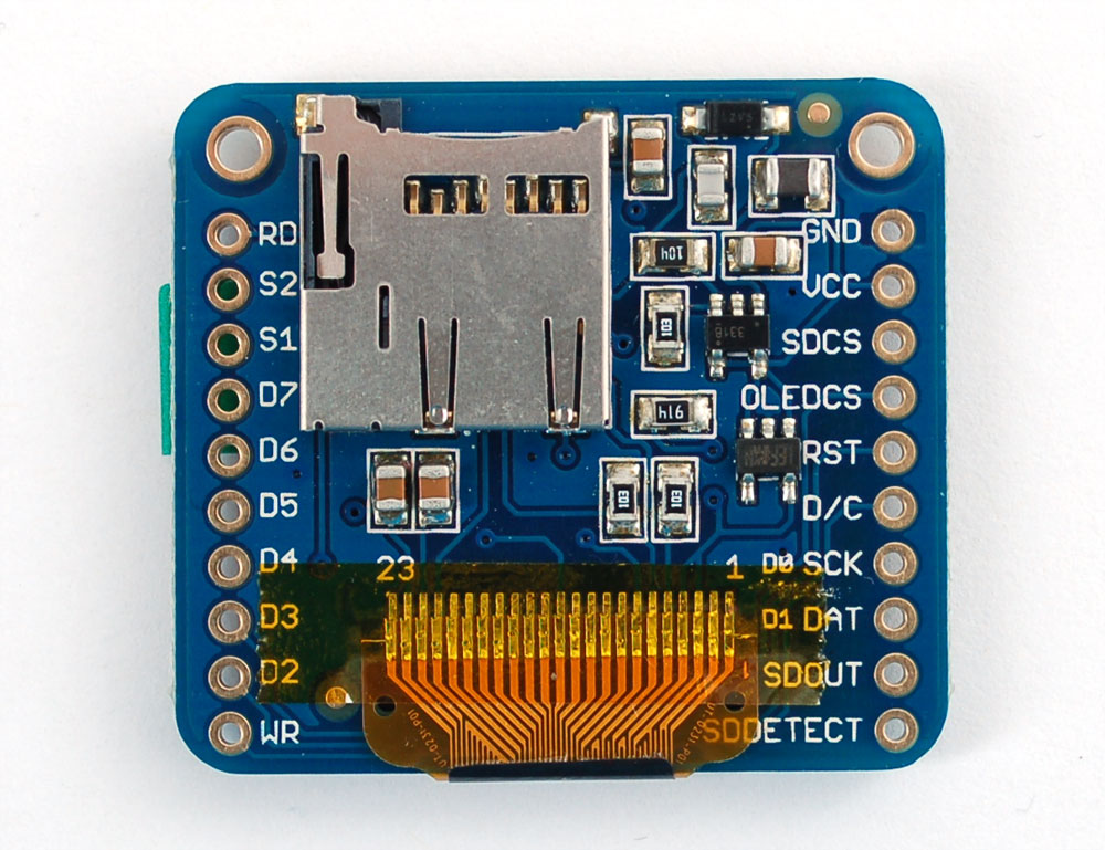
Starting from the top pin of the OLED (closest to the Adafruit flower) Connect the following OLED pins:
- Common ground - black wire
- 3.3V (red wires from the Arduino)
- SD CS Pin- don't connect (microSD card, we'll get to this later)
- OLED CS Pin - purple wire - 74LVC245 pin #17
- OLED Reset Pin - blue wire - 74LVC245 pin #16
- OLED D/C Pin - yellow wire - 74LVC245 pin #15
- OLED SCLK Pin - orange wire - 74LVC245 pin #14
- OLED DATA Pin - brown - 74LVC245 pin #13
- SD Detect Pin- not used, don't connect

Next we'll connect the remaining 74LVC245 pins to the Arduino
- Pin #1 goes to 3.3V (red wire)
- Skip
- Purple wire - goes to Digital #10
- Blue wire - goes to Digital #9
- Yellow wire - goes to Digital #8
- Orange wire - goes to Digital #13
- Brown wires - goes to Digital #11
- Skip
- Skip
- Connect to common ground
Then connect pin #20 of the 74LVC245 to 3.3V and pin #19 to Ground.
Digital #12 isn't used yet (we'll connect this to the SD card later
Now we can run the test software on the Arduino. We'll need to download the library first and install it
Visit the Adafruit SSD1331 library github repository page and click the DOWNLOADS button in the top right corner to download the ZIP file. Uncompress it and rename the uncompressed folder Adafruit_SSD1131. Check that the Adafruit_SSD1331 folder contains Adafruit_SSD1331.cpp and Adafruit_SSD1331.hPlace the Adafruit_SSD1331 library folder your <arduinosketchfolder>/libraries/ folder. You may need to create the libraries subfolder if its your first library. Restart the IDE.
You'll also have to install the Adafruit GFX graphics core library at this github repo and install it after you've gotten the OLED driver library.
After you restart, you should be able to select File→Examples→Adafruit_SSD1331→test - this is the example sketch that just tests the display by drawing text and shapes. Upload the sketch and you should see the following
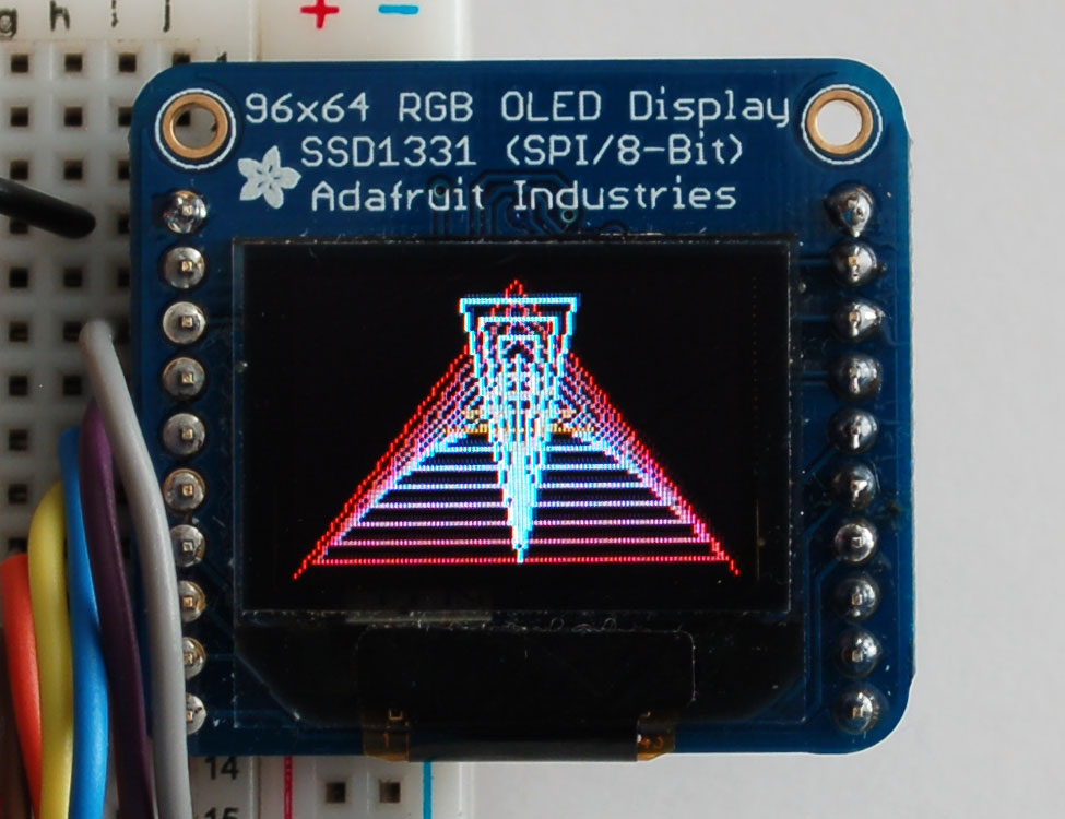
If alls working, then you can start looking through the test sketch for demonstrations on how to print text, circles, lines, etc
Drawing Bitmaps
We have an example sketch in the library showing how to display full color bitmap images stored on an SD card. You'll need a microSD card such as this one . This example will only work for Arduino v1.0 and later.
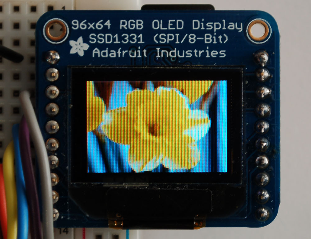
You'll also need an image. We suggest starting with this bitmap of a flower If you want to later use your own image, use an image editing tool and crop your image to no larger than 64 pixels high and 96 pixels wide. Save it as a 24-bit color BMP file - it must be 24-bit color format to work, even if it was originally a 16-bit color image - becaue of the way BMPs are stored and displayed!
Copy the violet.bmp to the microSD card and insert it into the back of the breakout board
We'll have to add an extra 2 wires so we can 'select' and 'receive data' from the SD card
Connect the third pin SD ChipSelect of the OLED (gray wire) to pin #18 of the 74LVC245. Then connect pin #2 of the 74LVC245 to Arduino Digital #4. This is the pin to select that we want to talk to the microSD card.
Then connect second-from-the bottom pin of the OLED - SDOUT - with a wire directly to Arduino Digital #12 this is the longer white wire
shown - this wire does not need to be level shifted.
You should see the daffodil! If you don't see it, check the Serial Monitor for hints on what might have gone wrong (maybe the microSD card had an issue)
Download
- You'll also have to install the Adafruit GFX graphics core library at this github repo and install it after you've gotten the OLED driver library.
