The simplest of all programming interfaces is the PPI. It plugs into the parallel port and has a few resistors (to provide basic protection to your computer. Nothing is easier or cheaper, but it requires that your PC has a parallel port.

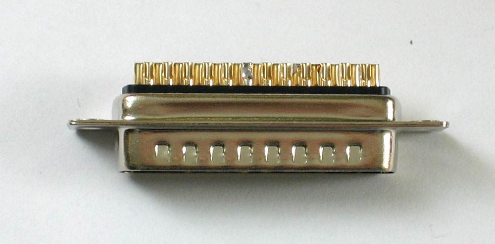
This is what a parallel port looks like, often called a "printer" port
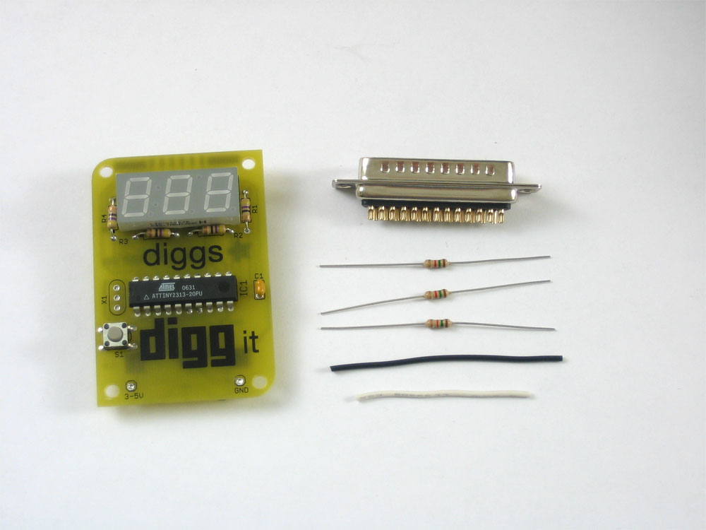
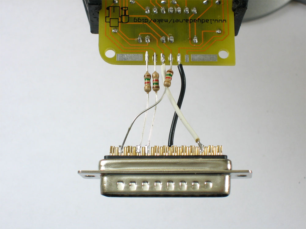
Get a DB-25 male connector (which will mate with the DB-25 female connector on your computer) available from Digikey, Jameco and RadioShack or any other electronics/computer repair/hobby shop for ~$2. Also find some plain insulated wire and 3 resistors, around 1Kohm (the ones here are 1.5K) you can get the resistors at Digikey or RadioShack too.
Then follow these instructions, you can always click on the pictures to get a bigger version if the details arent clear.
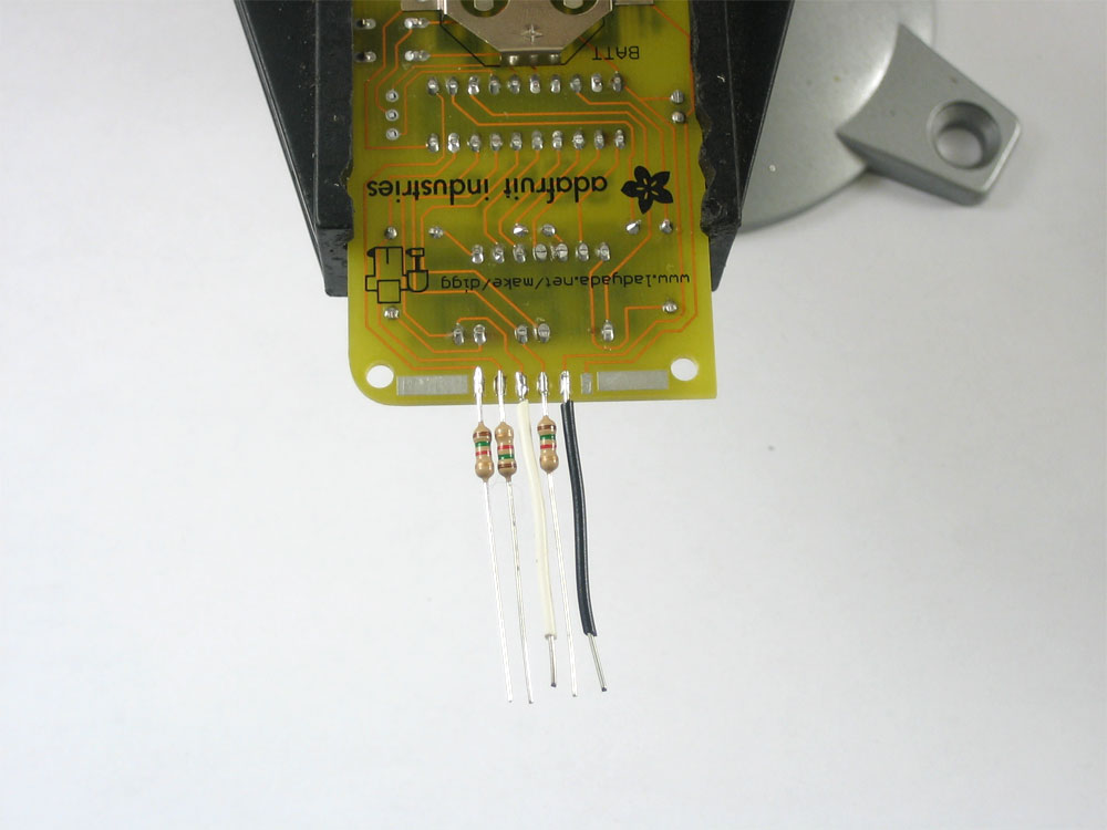
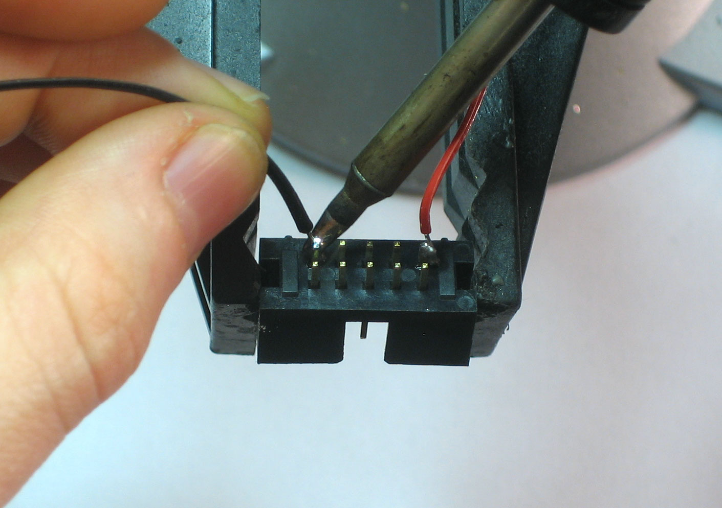
Solder the 3 resistors and two pieces of wire as shown. The rightmost tab doesnt connect to anything.
Melt some solder into the DB-25 connector onto pins #2, 4, 5, and 11
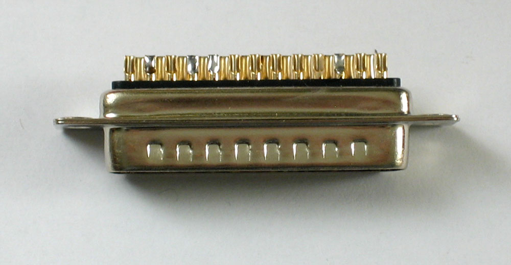
On the other side solder pin #20
Solder the black wire to pin #20
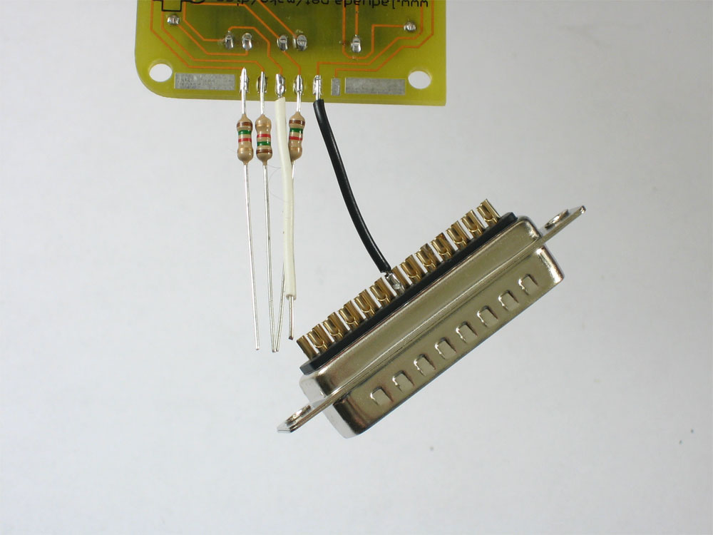
Solder the white wire onto pin #11

Solder the leftmost resistor onto pin #4

Solder the second resistor from the left to pin #5 and the third resistor to pin #2
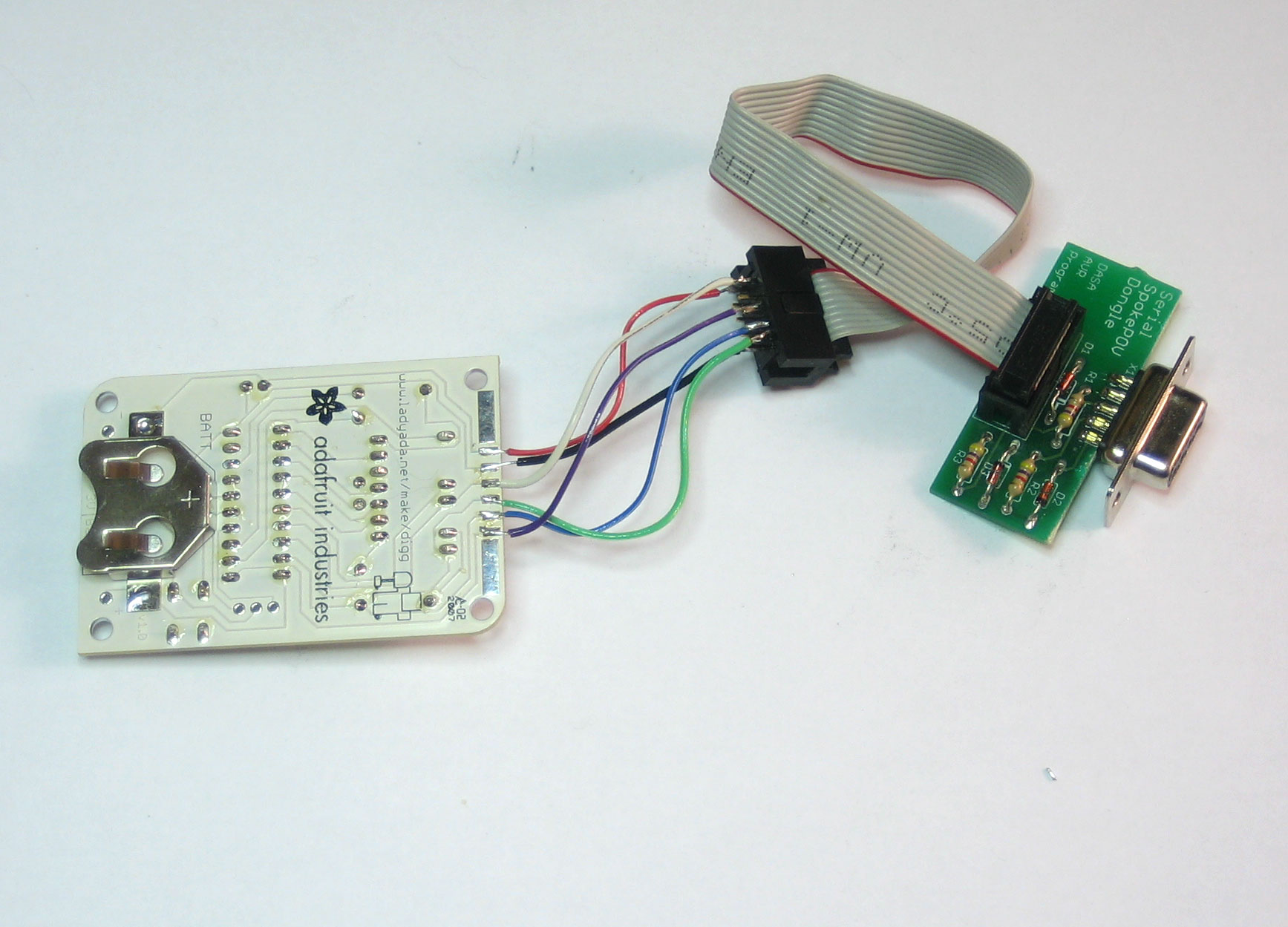
Attaching a programming header means you can plug in a serial port or USB programmer.
There are 2 standard pin outs that AVR chips use to interface
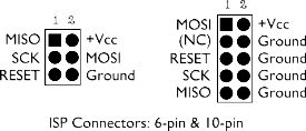
You can use either but for this demo I'll be using the 10-pin version since all the programmers in my shop have a 10-pin cable and most programmers and dev-boards do too.
You will need a 10-pin programming header (alternately a piece of dual row 0.1" header will suffice, but this one has a nice plastic box around it to keep you from plugging it in wrong) and some wire.
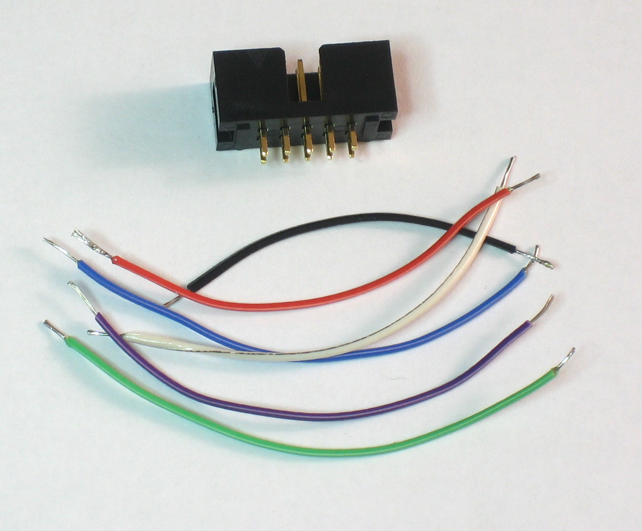
Place the boxheader in a vise, note which way the notch goes.
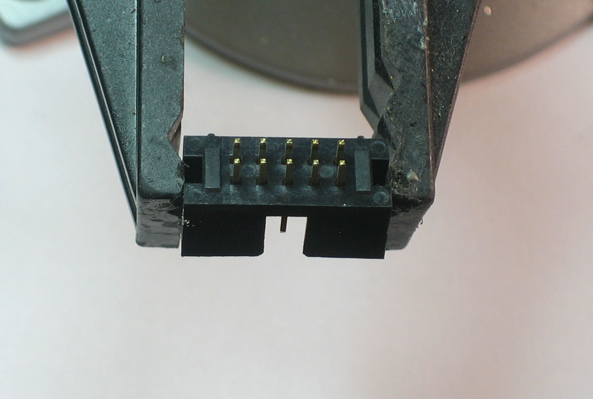
With a soldering iron, tin the legs so itll be easier to solder to them.

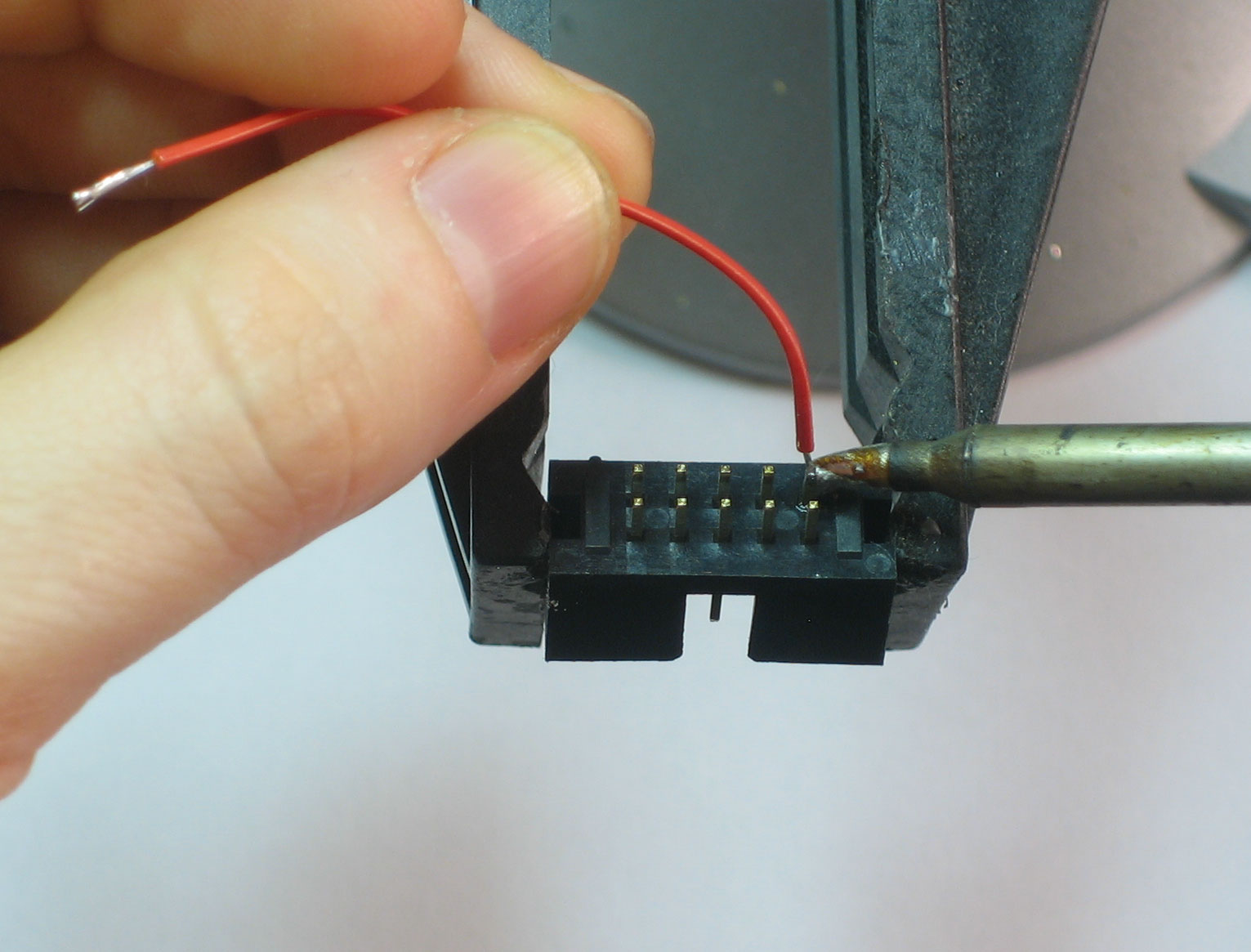
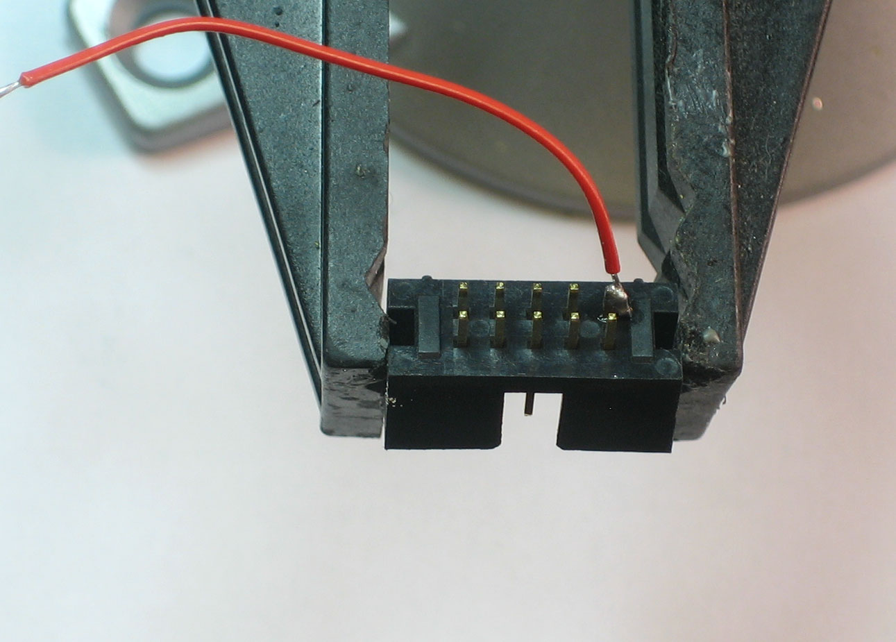
Solder the VCC (power) wire
Next, the GND (ground) wire
Next the MOSI (Serial In) wire

Next, the RESET wire
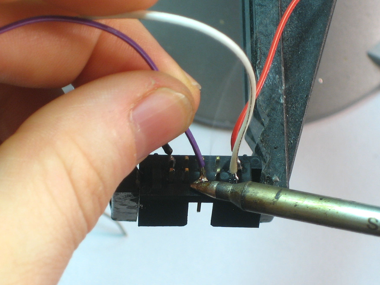
Next the SCK (Serial Communications Clock) wire

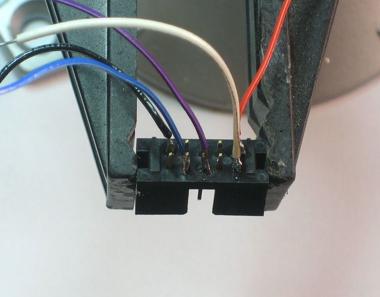
Lastly, the MISO (Serial Out) wire

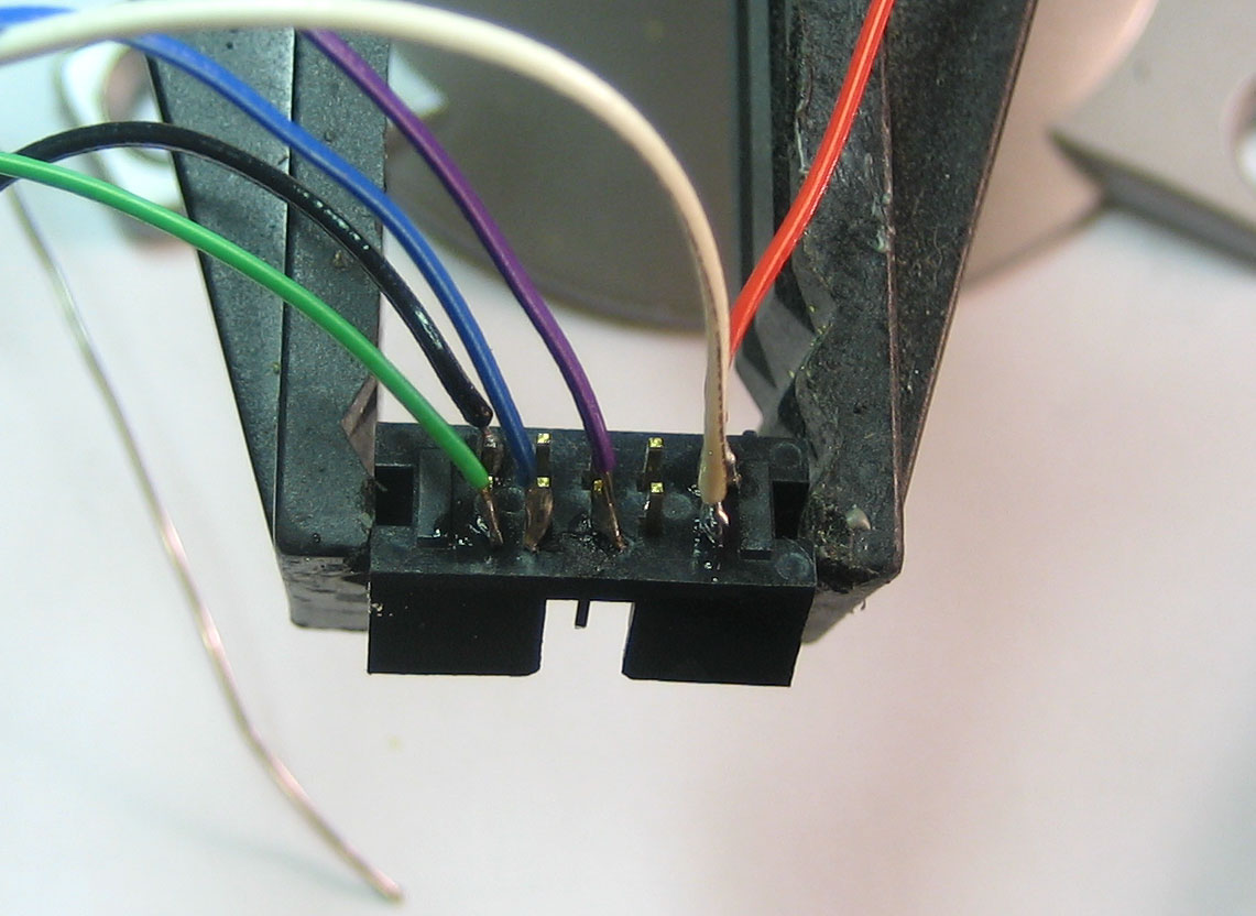
OK done!
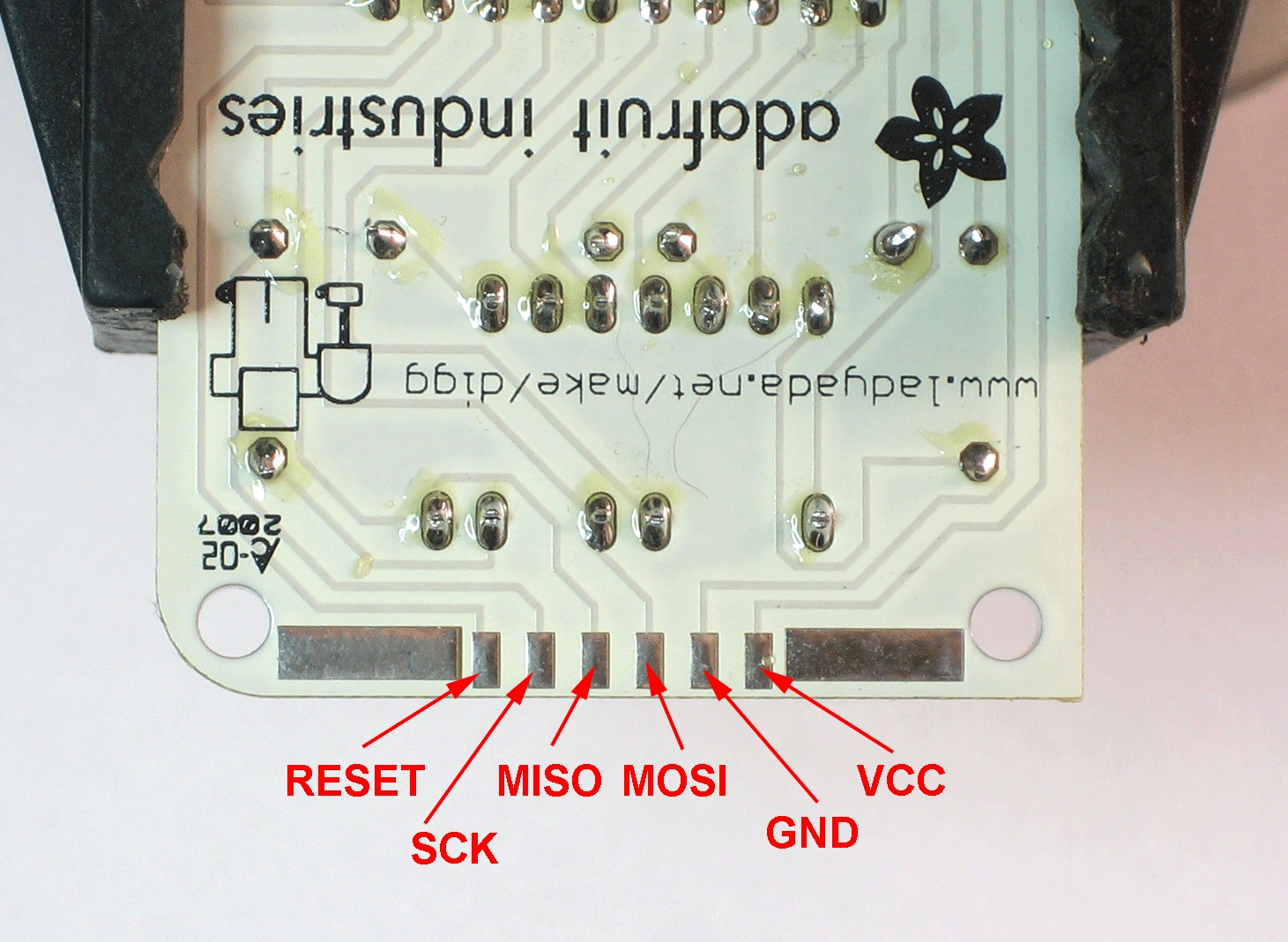
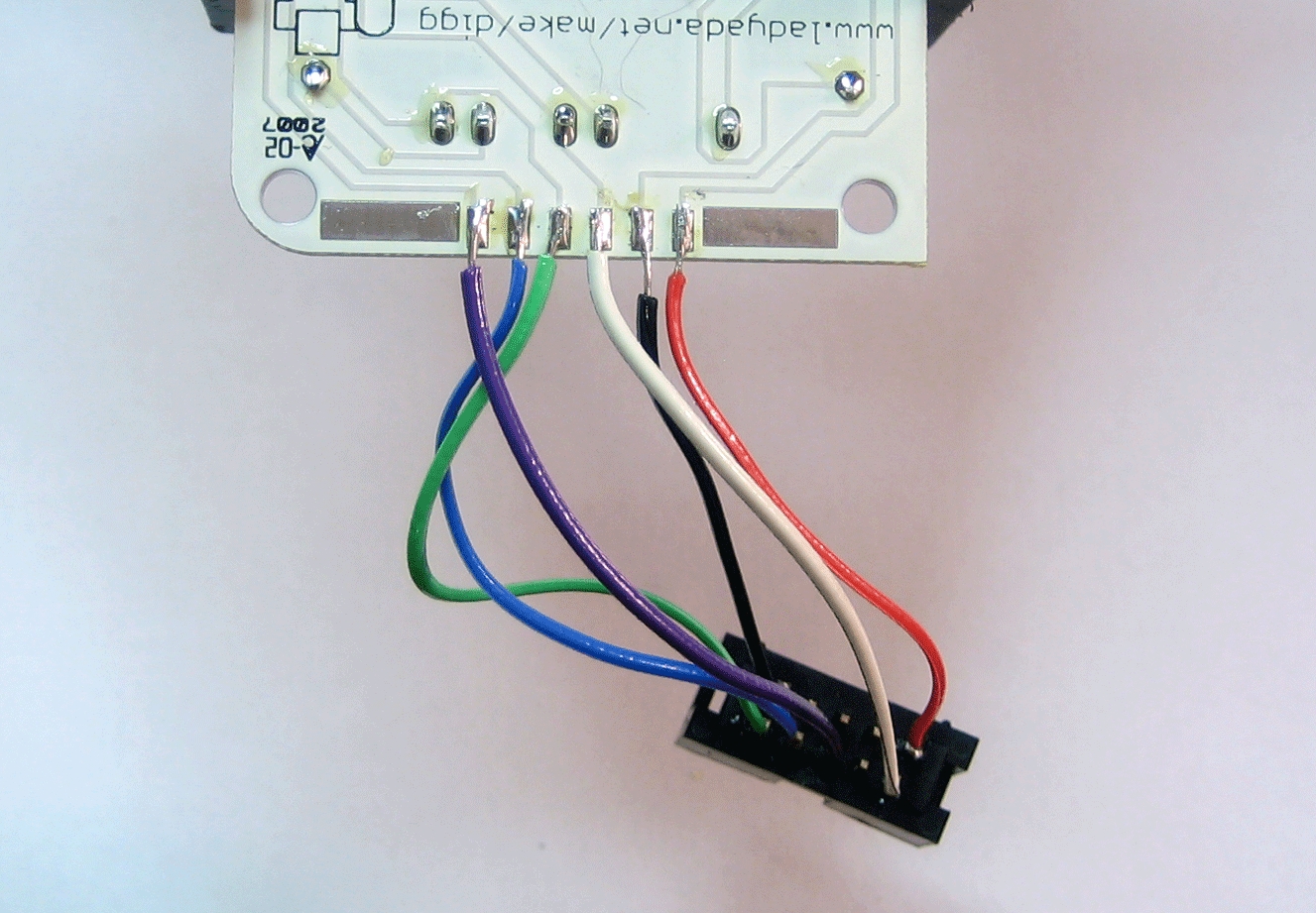
Next, we must connect the header to the chip, you can look up the pins in the datasheet but its simpler to just look at this diagram
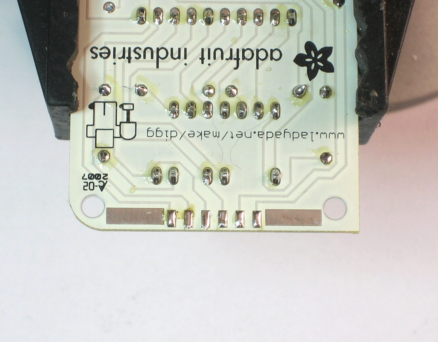
Prep the PCB fingers by melting a bit of solder on each pad

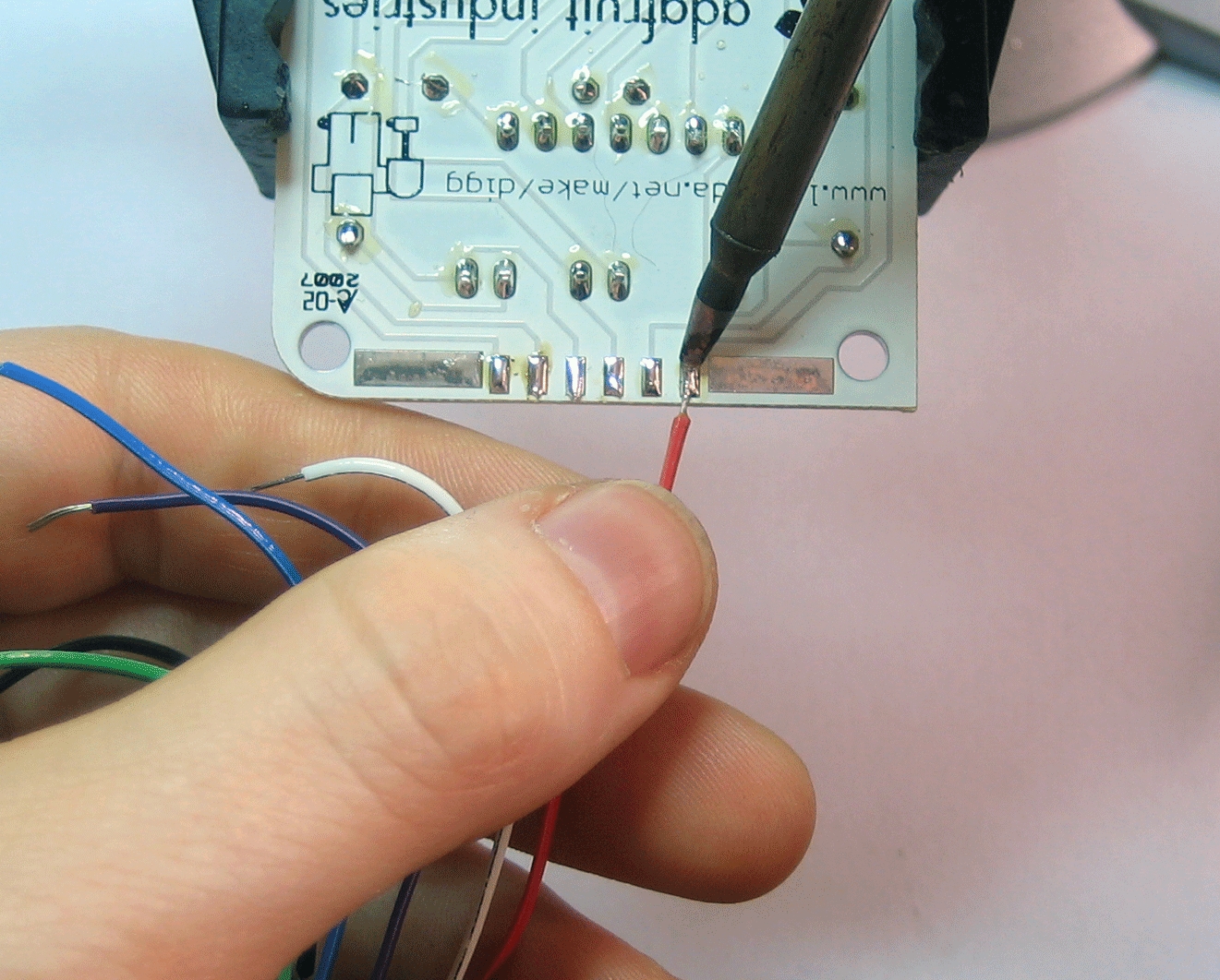
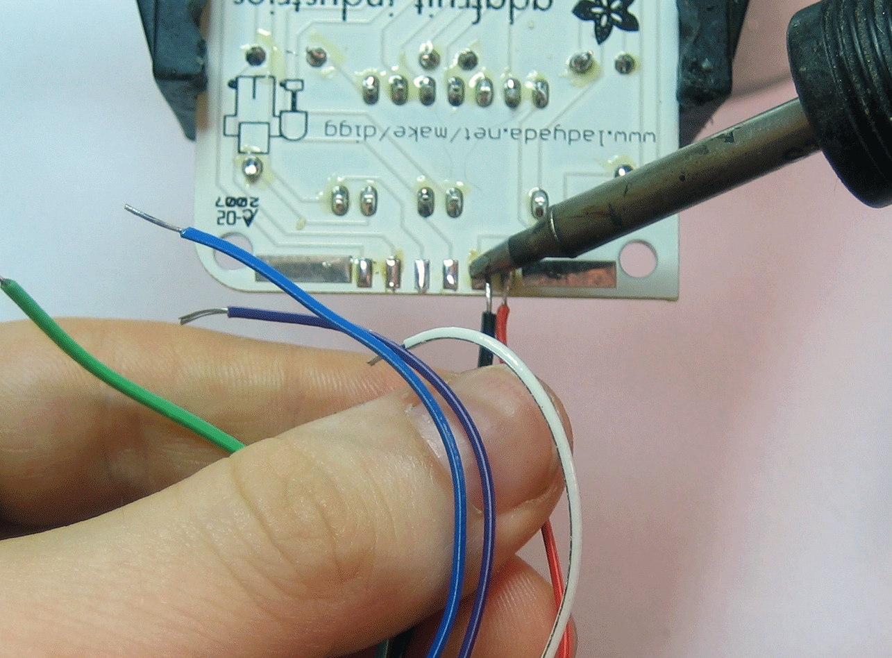
Next solder the wires from the header onto the fingers

Now you can connect up a serial port, parallel port or USB port programmer!