 |
Get ready by placing the PCB in a vise |
 |
We're going to the SD card first. While surface mount parts are a little tougher than thru-hole, this piece has pin spacing of 0.1" so it is quite easy. Doing it first also gives us lots of working room. The holder should 'snap' perfectly into place thanks to two bumps on the bottom. |
|
We'll start with the four side tabs that are used to mechanically secure the card holder in place. Heat up the metal tab and the pad (the silver square beneath it) for 3 seconds with a hot soldering iron, then poke just a bit of solder in. Do this for all three corners. Once this is done you should not be able to lift the card holder |
|
Now go thru and solder the 8 leftmost pins that stick out from the holder. The three rightmost pins are thinner and closer together so they are tougher to solder. Luckily they are not used and you simply skip them (although the photo shows them done) Check that you have no solder bridges - the pins should not be soldered to the metal body of the holder or to each other |
|
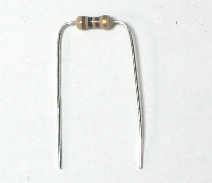
Next, we will solder all of the many resistors. The 10K resistors R2 and R4 are first. Form them into staples, then place them so they sit flat against the PCB, in the correct locations. Resistors don't have polarity so they can go in 'either way' and work fine! Once placed, bend the leads out so the resistors dont fall out |
|
Solder the leads to the pads (metal ring) by heating both with the side-tip of the iron for 3 seconds and then poking in a bit of solder |
 |
Use your diagonal cutters to clip the leads off just above the solder joint |
 |
Next place the three 4.7K resistor R3 R5 and R6 Make sure they go in the right locations! |
|
Solder and clip the leads of the three resistors |
 |
Finish up the resistors by placingR8 (100Kohm), R1 (1.0K) and R7 (1.5K) In the photo, R1 is shown as 1.5K...this is a mistake! (It was too flakey for me and I reduced the resistance). Make sure you place a 1.0K resistor in R1! Solder the components |
 |
Next comes the 3.6V zener diode. A diode is sort of resistor-shaped except that it has a black stripe on one end. Diodes are polarized and must be placed the correct way to work so make sure that the black stripe on the diode matches the white stripe on the silkscreen position indicator |
 |
Next is the 0.01uF ceramic capacitor C8. The tricky part here is that there are many 0.1uF ceramic capacitors that look identical! The way to tell the difference is look for the 103 printed on it. If it says 104 then it's a 0.1uF. This capacitor forms the output low-pass filter for the audio so its important to have the right value. |
 |
Place the capacitor right next to R7. Ceramic capacitors are non-polarized and can go in 'either way' |
|
Solder and clip the small capacitor leads |
 |
Once you're sure you have C8 correct, you can place the remaining 0.1uF ceramic capacitors C2, C3, C6, C6 and C7. Ceramic capacitors are non-polarized and can go in 'either way' |
|
Solder and clip the capacitors |