A microcontroller is, essentially, a chip that has a program burned into its flash memory. When power is given to the device, it runs the program. A microcontroller can often perform many functions in parallel, such as reading sensors via an A/D, displaying on an LCD, processing data, interacting with other chips, etc. by using interrupts. They're a powerful electronics development tool because they are very inexpensive (on the order of a few bucks), have ROM, RAM, EEPROM, and a processor core already integrated, and can be programmed using popular languages such as C, BASIC and assembly. For this reason, I find them to be an excellent introduction to electronics for those who have some experience with computers and software.
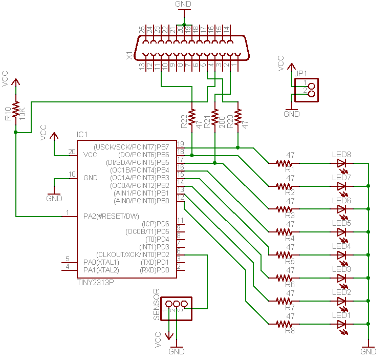
The microcontroller used for the MiniPOV2 is an Atmel 20-pin RISC device called the ATtiny2313. This chip was chosen because it is the cheapest one that has an internal oscillator (no external crystal/clock necessary) and enough I/O pins to give every LED a pin.
LEDs are current driven. That is to say, one should design the circuit with a given amount of current going through every LED instead of deciding what the voltage across the LED is. Basically this means one needs to have a resistor in series with the LED, and the larger the resistor, the less current. Pretty much every LED function best with approximatly 5mA to 20mA of current running through them.
To calculate the resistor size, first one must determine what the (a) supply voltage is and (b) what the LED voltage drop is. For MiniPOV, (a) is 3V since each AA battery provides 1.5V. For (b), one looks up the 'forward voltage drop' in the datasheet. This value is dependant on what the LED is made out of, which also determines the color. Pretty much all red LEDs have a forward drop of 2V. Blue, white, UV and some green LEDs have a forward drop of 3.4V. Note that, in general, the supply voltage must be larger than the forward drop for the LED! Now subtract the two and divide by the current to get the resistor size in ohms: (3V - 2V / .02A = 50 ohms.) Since these resistors 'choke' off the amount of current going thru the LEDs, they are called 'choke resistors'
There are a few easy to use LED calculators online.
Since a parallel port can send/receive 5V signals (serial ports are +-10V), they are well suited to interface with a microcontroller. Also, virtually every PC has a parallel port (Its the female DB-25 port on the back. (Sadly, Macs don't...) PIC microcontrollers need a 12V signal to program, but Atmels don't. Thus, the 'direct parallel programmer'! The particular wiring order used in the MiniPOV is refered to as the "DT006" style, named after a DonTronics kit that uses it. To program chips using this interface, the popular "AVRDUDE" (which has been ported to native Windows) and "uisp" (linux, BSD, etc) programs may be used.
The MiniPOV2 kit comes with a 2xAA battery case. The resistor values were chosen with the expectation that you'll use alkalines, but rechargables should be OK too. In fact, any high-capacity 2.5 to 5VDC supply can be used (but certainly not a 9V!). Of course, if the voltage goes up, the choke resistors for the LED have to be larger to keep the same brightness.
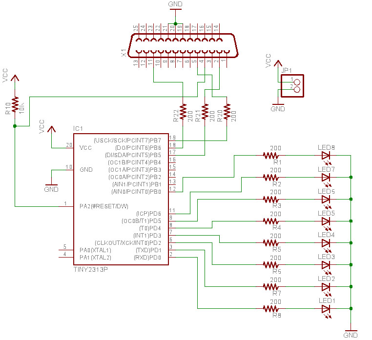
The older version (v2.0) had a different schematic.
| Name | Description | Qty |
| IC1 | ATtiny2313 Microcontroller 20-DIP | 1 |
| IC1* | 20 Pin Socket | 1 |
| R10 | 1/W 10K resistor | 1 |
| R1-9, R20-22 | 1/4W 47ohm resistors (adjusted depending on LED) | 11 |
| U1 | 2 AA Battery Case with switch | 1 |
| D1-8 | Red oval LED | 8 |
| X1 | DB-25 male connector w/solder cup connectors | 1 |
| PCB | Silk screened, 2 sided PCB | 1 |