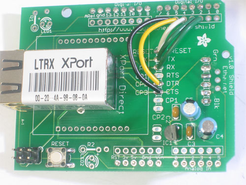
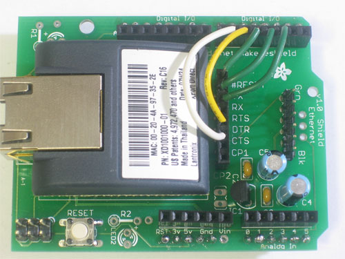
V1.0 of the PCB has an error in the silkscreen, for the XPort direct labels, CP1 and CP2 are -swapped-. The labels for the XPort side are OK.
The labels, reading down, should be #RESET, TX, RX, RTS, DTR, CTS, CP2, CP1
This will be fixed in v1.1, sorry!
Since all of the XPort communcation happens with "software serial", its up to the user to decide which pins on the Arduino to connect up to the XPort.
Since all of the examples that will be posted on this site will use the same configuration, I will show how to wire up the XPort in the following way:
- XPort RX pin -> Arduino digital pin 2
This is the pin that the XPort uses to receive data. It is necessary! - XPort TX pin -> Arduino digital pin 3
This is the pin that the XPort uses to send data. It is necessary! - XPort Reset pin -> Arduino digital pin 4
This is the pin that is used to reset the XPort. It is necessary! - XPort DTR pin -> Arduino digital pin 5
This is the pin that the XPort uses to tell the Arduino that the Internet connection has ended. Its not essential but its very useful - XPort CTS pin -> Arduino digital pin 6
This is the pin that the Arduino uses to keep the XPort from overwhelming it with data. Its not essential but its very, very strongly recommended - XPort RTS pin -> Arduino digital pin 7
This is the pin that the XPort uses to tell the Arduino that there is more data available. Its not used in my examples but it might be useful for some people.
If you decide to go with something else, make sure you change the example code below in the example sketches. If the pins are not used, set the number value to "0" (zero)
#define XPORT_RXPIN 2
#define XPORT_TXPIN 3
#define XPORT_RESETPIN 4
#define XPORT_DTRPIN 5
#define XPORT_CTSPIN 6
#define XPORT_RTSPIN 7
Simply solder plain wires between the row of pads next to the XPort and the row of pads along the header connection
Or, if you want to get fancy and you have female socket header in your spare-parts bin, you can use that!


