These are the instructions for v1.1 ONLY! If you have a v1.0 kit, DONT use these instructions! Check out the v1.0 instructions
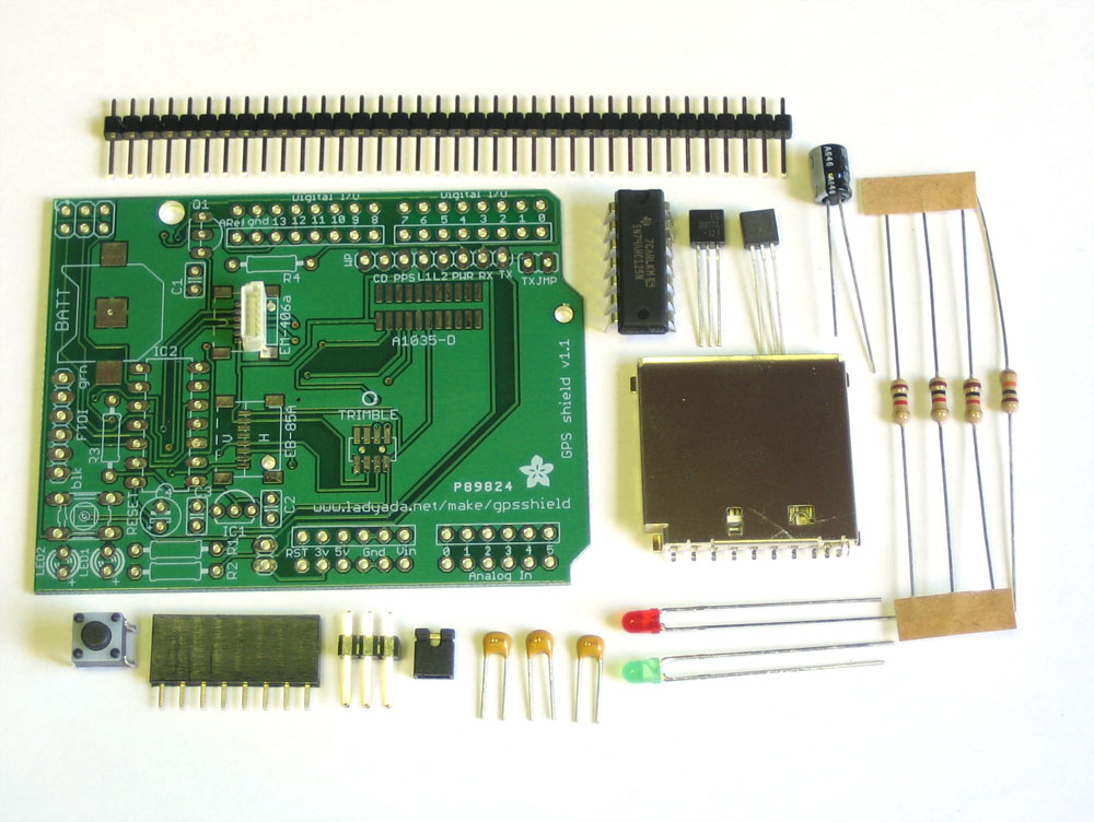 |
Check that you have all of the components for the shield. The full parts list (BOM) is available here. |
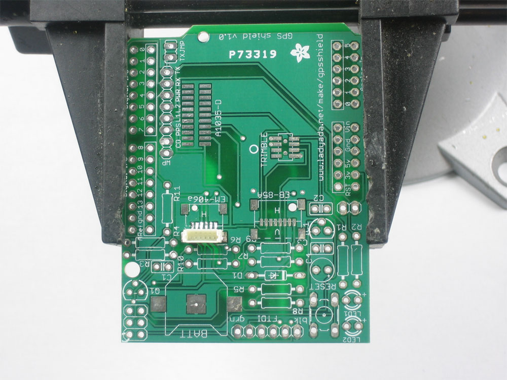 |
Get ready by placing the PCB in a vise Heat up your soldering iron to 700deg F, clean the tip and make sure your sponge is wet If you are building the shield from a kit, you'll notice that the small 6-pin JST connector is pre-soldered. If you bought just a PCB or are making your own, use surface mount soldering techiques to solder the connector you are planning to use. Lets go! |
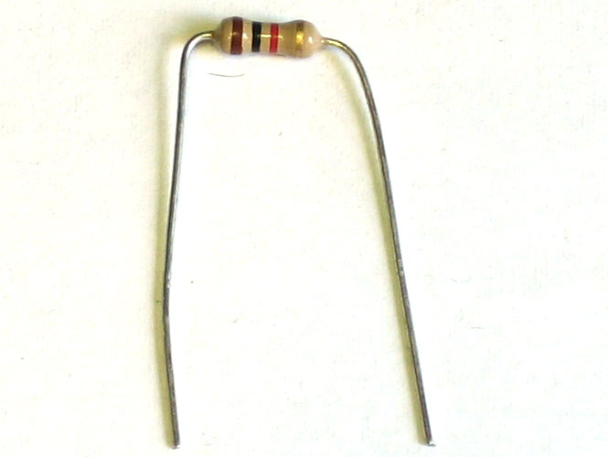 |
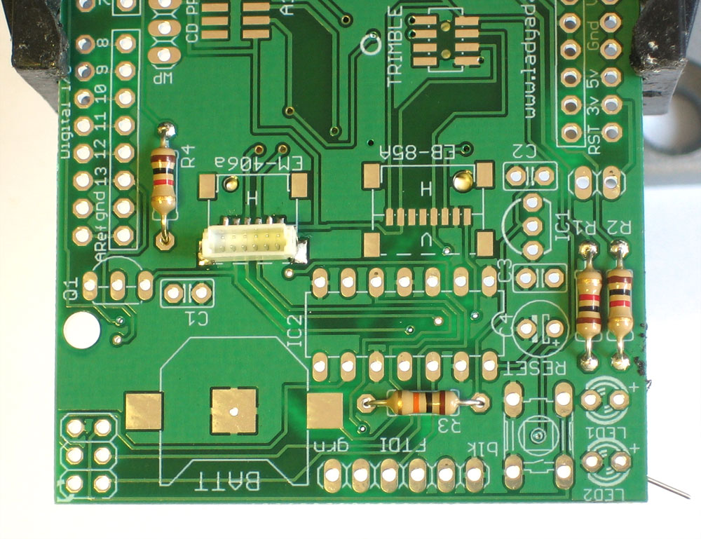
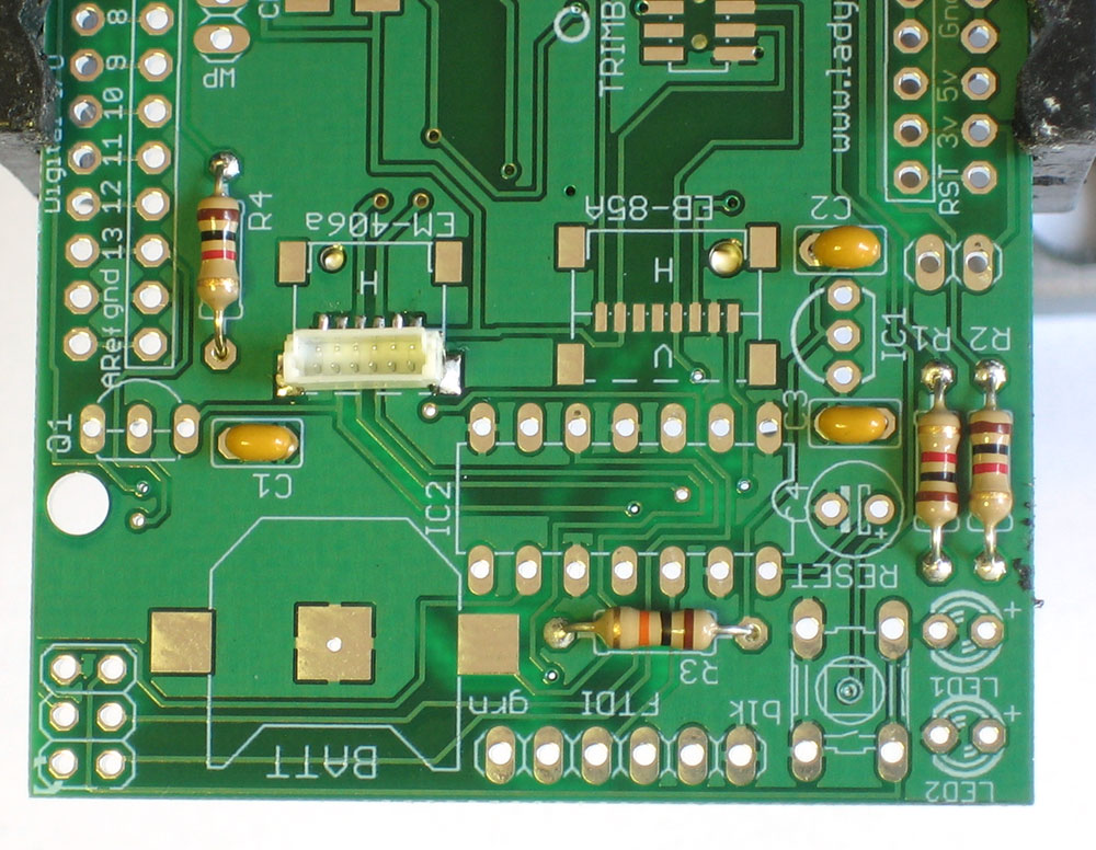
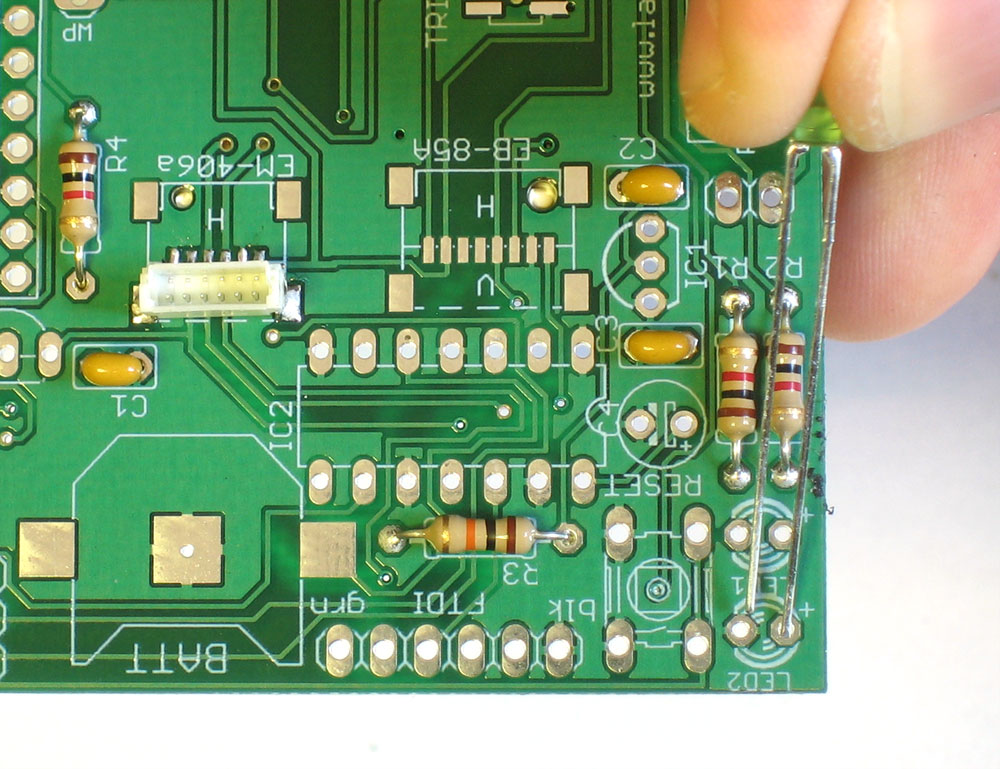
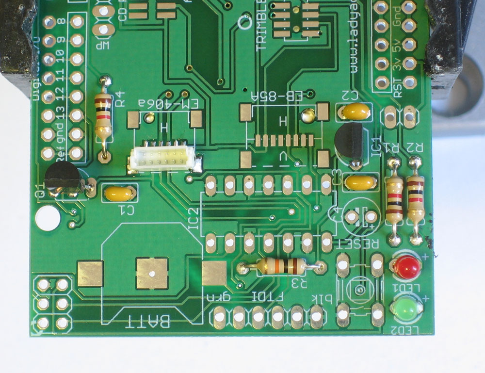
The first part we're going to solder is a 1K resistor. The 1.0K resistor is striped Brown Black Red Gold. Bend the resistor into a staple as shown.
|
 |
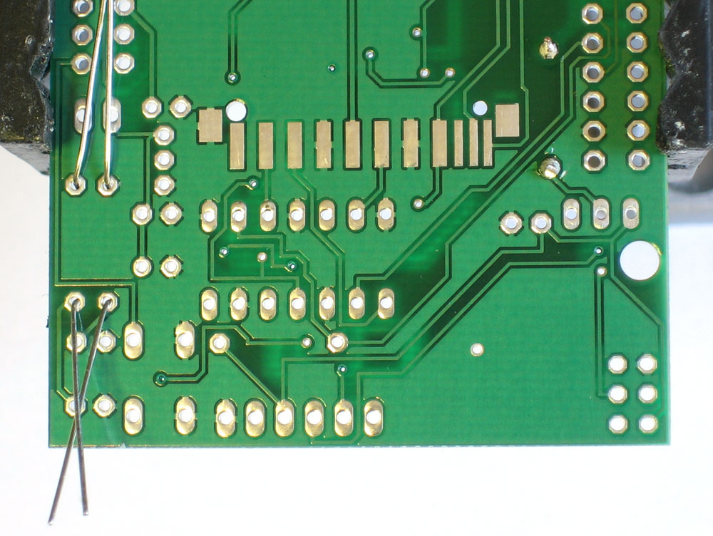
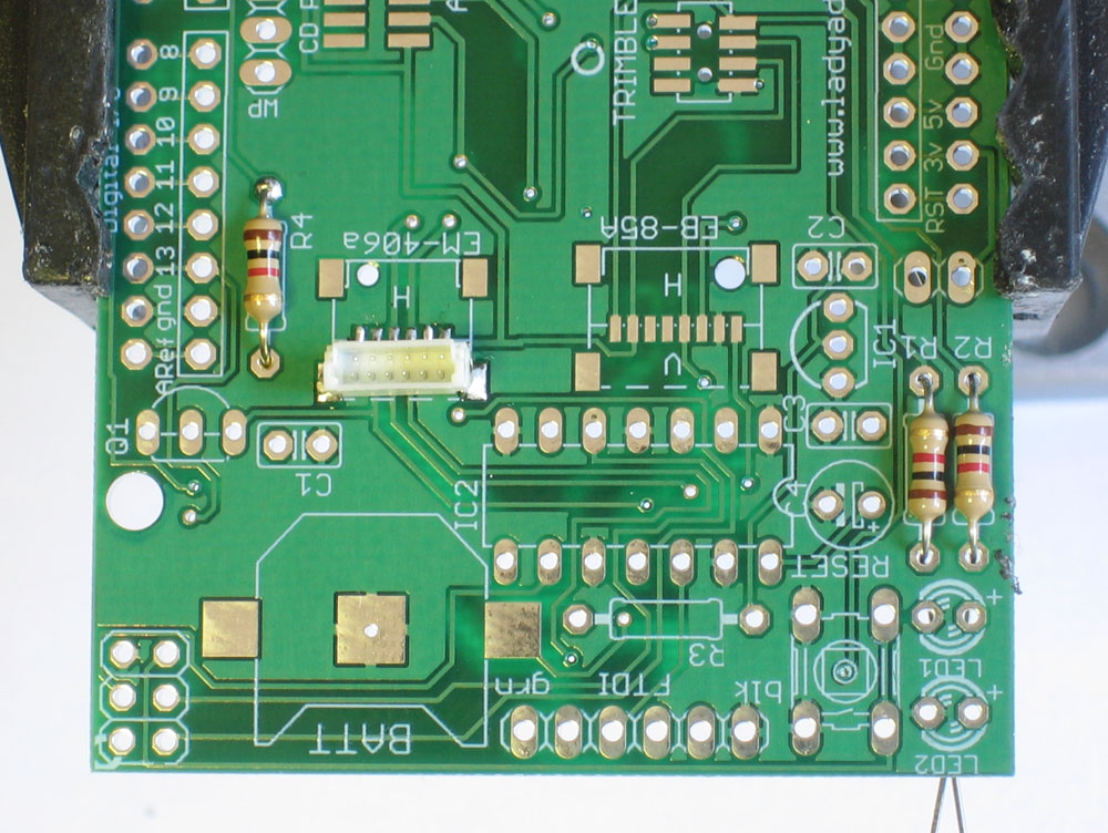
Place the resistor in the location marked R4. Resistors do not have polarity which means you can put it in 'either way' and it will work just fine. Bend the wire legs out so that the resistor sits flat against the PCB. |
|
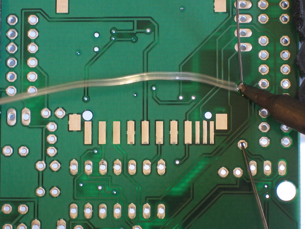
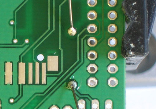
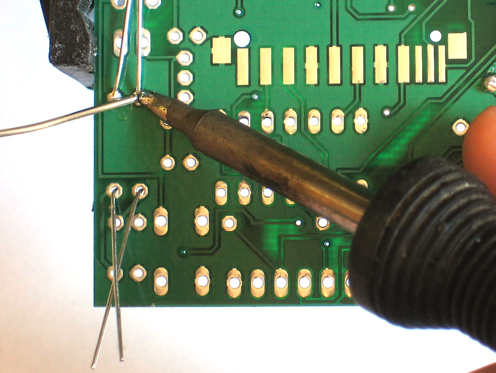
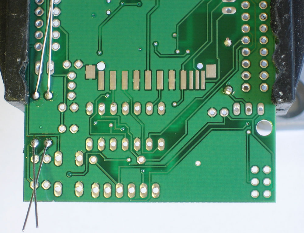
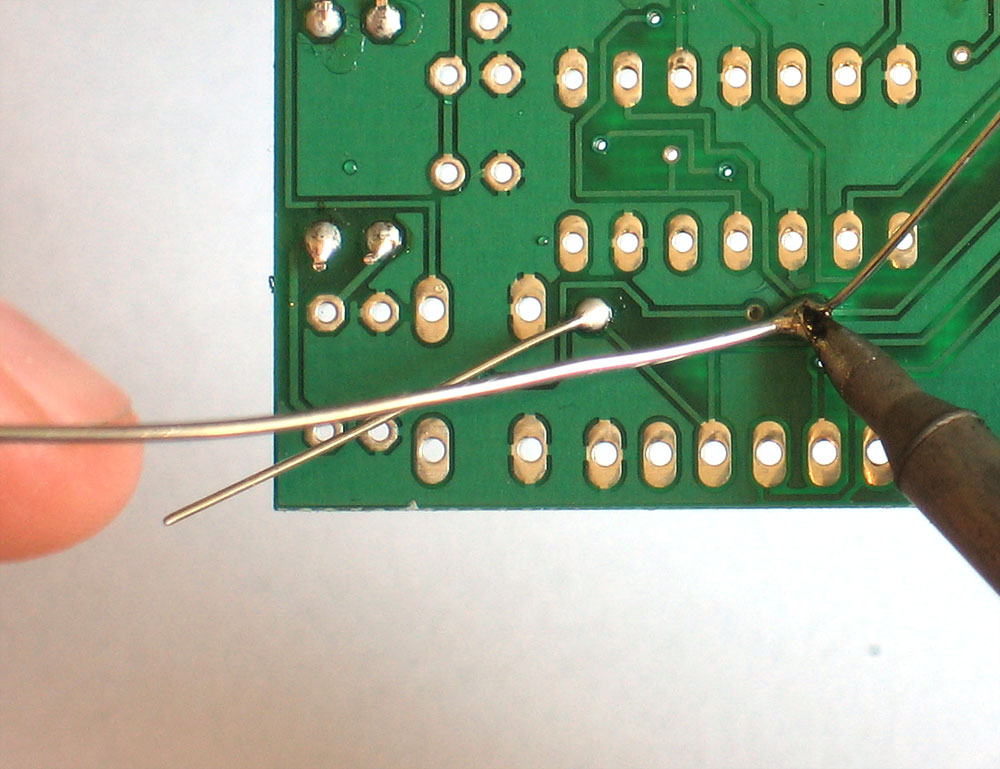
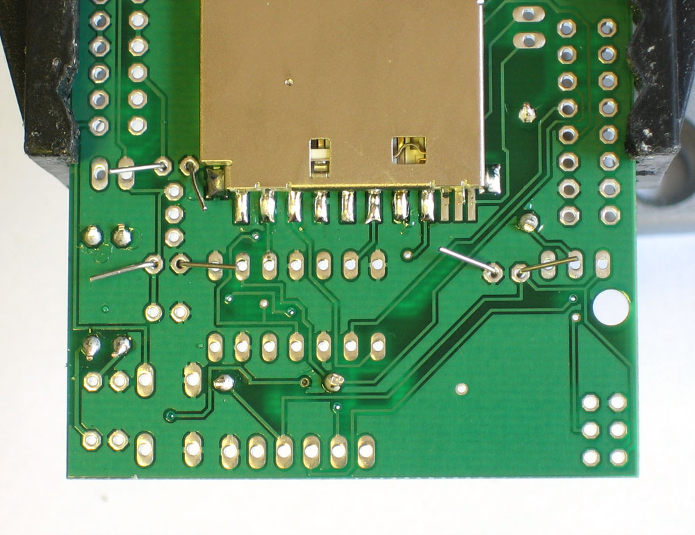
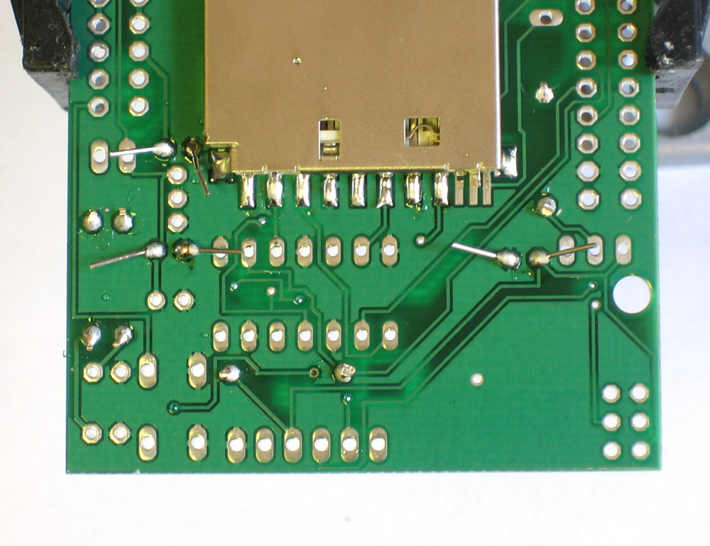
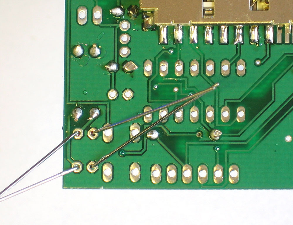
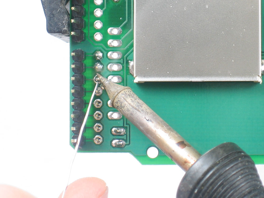
Turn the PCB over. Using your soldering iron tip, press and heat both the pad (the silver ring around the hole) and lead (wire) at the same time for 2 or 3 seconds. Then poke the end of the wire into create a nice solder joint. Do this for both leads. |
|
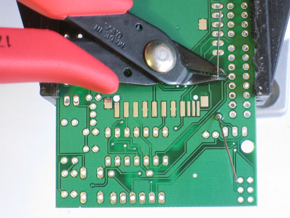
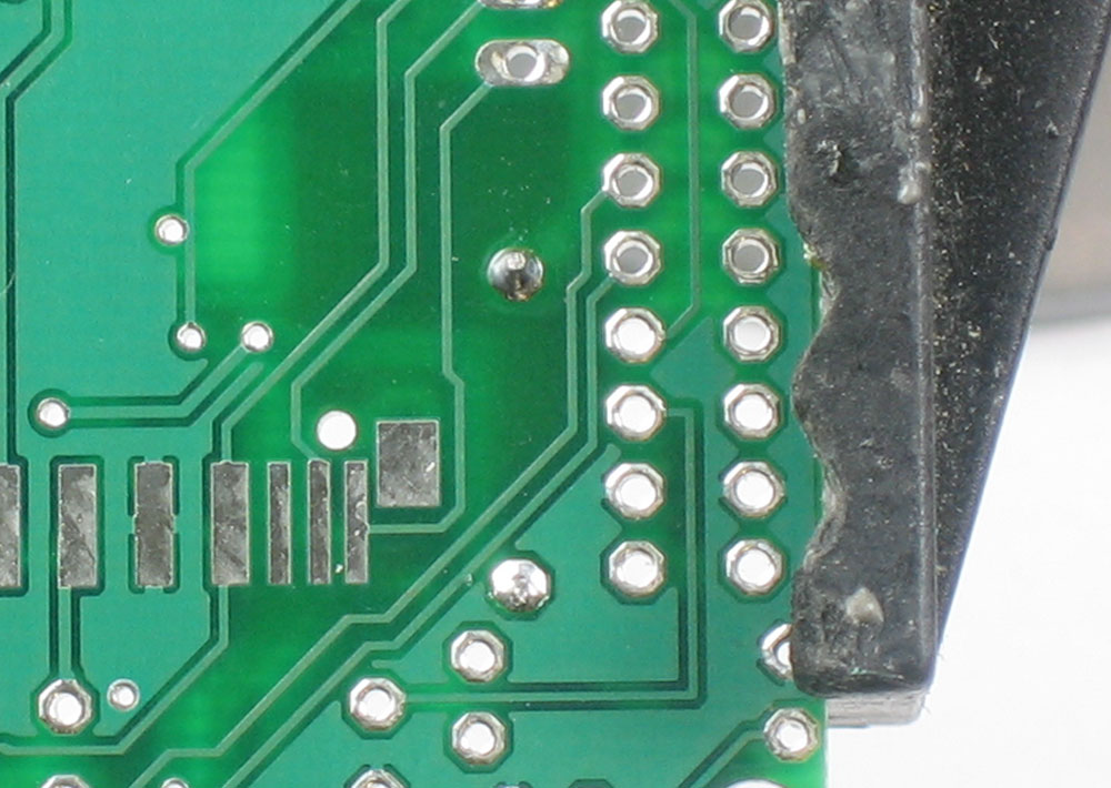
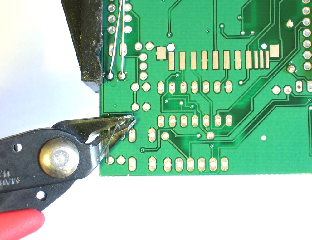
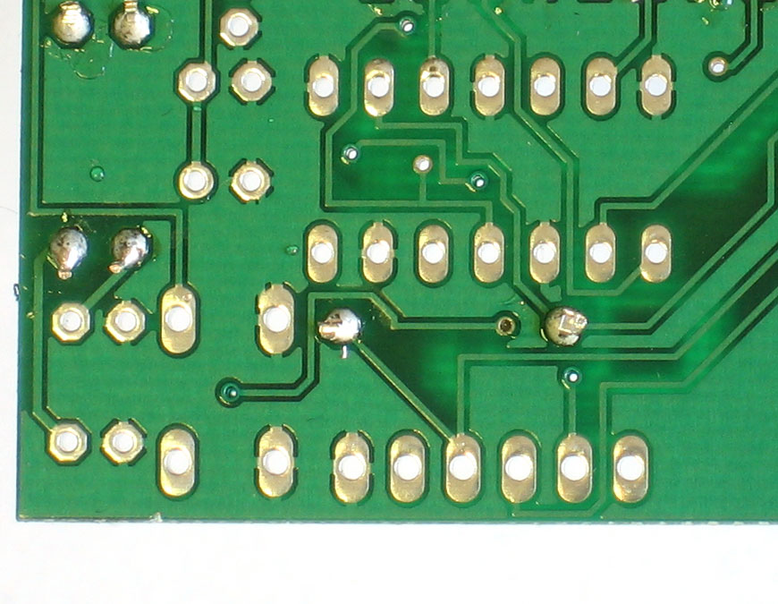
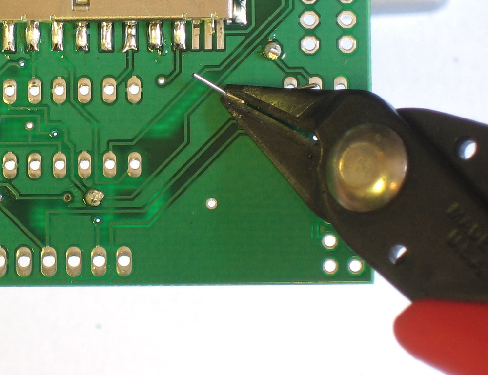
Using your diagonal cutters, cut off the long leads just above the solder joint. |
 |
Repeat for the two other 1K resistors, R1 and R2 |
|
Flip over the PCB and solder the 2 resistors. |
|
Clip the two resistors' leads |
|
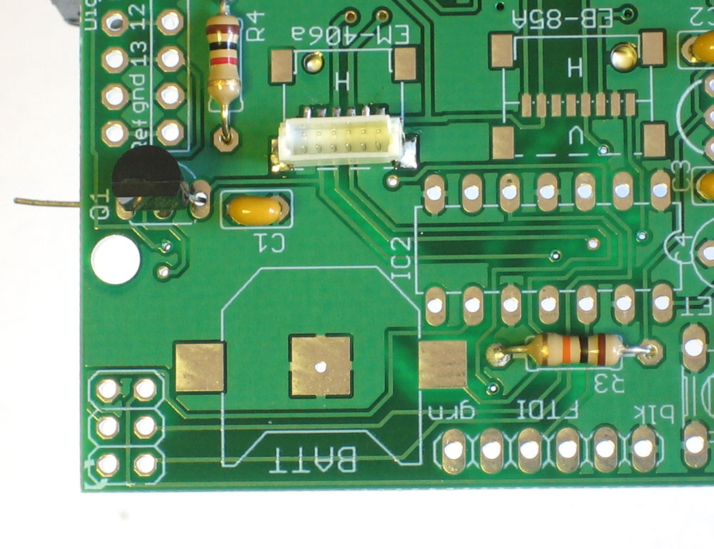
Next is the final resistor, this one is a 10K resistor R3 |
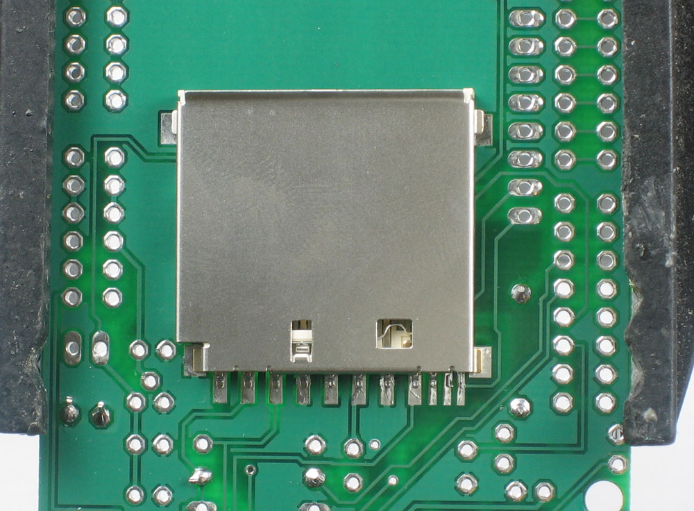 |
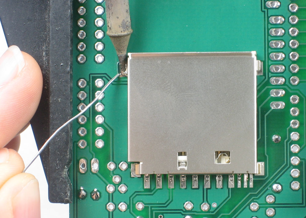
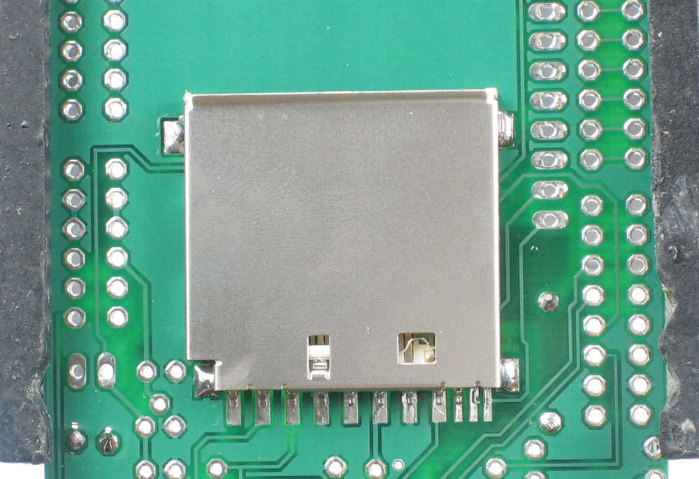
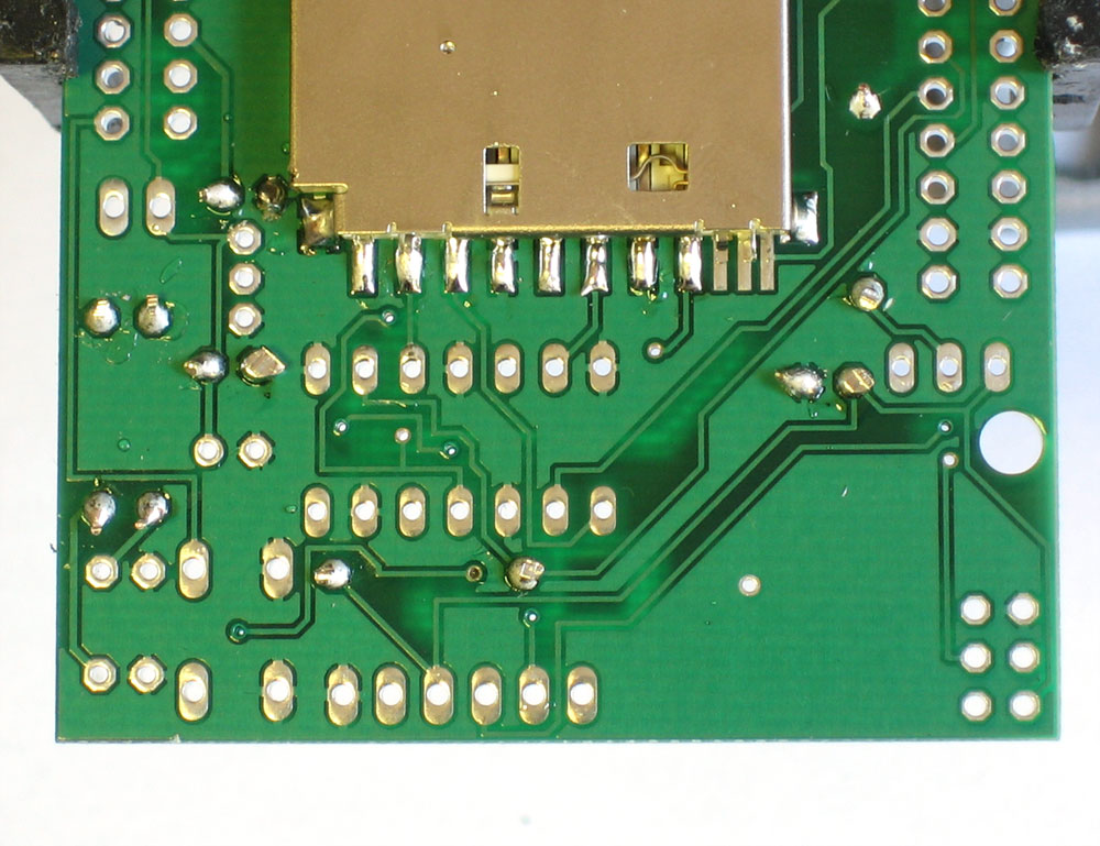
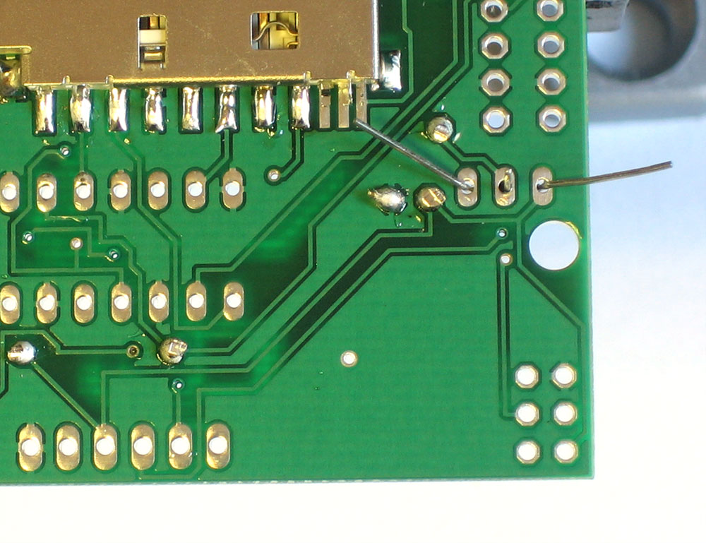
Once you are feeling comfortable with the resistors, lets do the SD card holder. The holder is surface mount (there are no wires that go through the board) but the spacing is very generous, so it wont be difficult. The holder has two bumps that 'snap' into place on the PCB. Make sure that the bumps are engaged and the holder is sitting flat. |
|
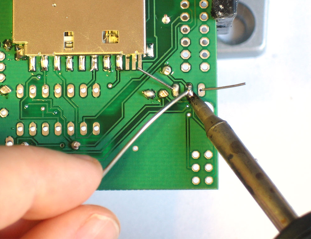
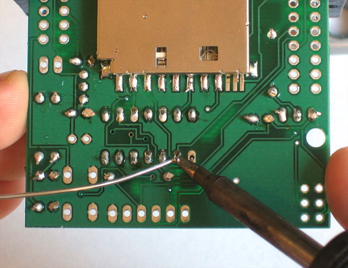
The first step to soldering the holder is to 'tack' it in place. On the sides are 4 large tabs. Heat both the pad and tab together for 3 seconds and solder the tab down. Repeat for all 4 tabs. When you're done you shouldn't be able to move the holder. |
|
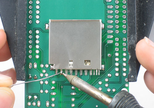
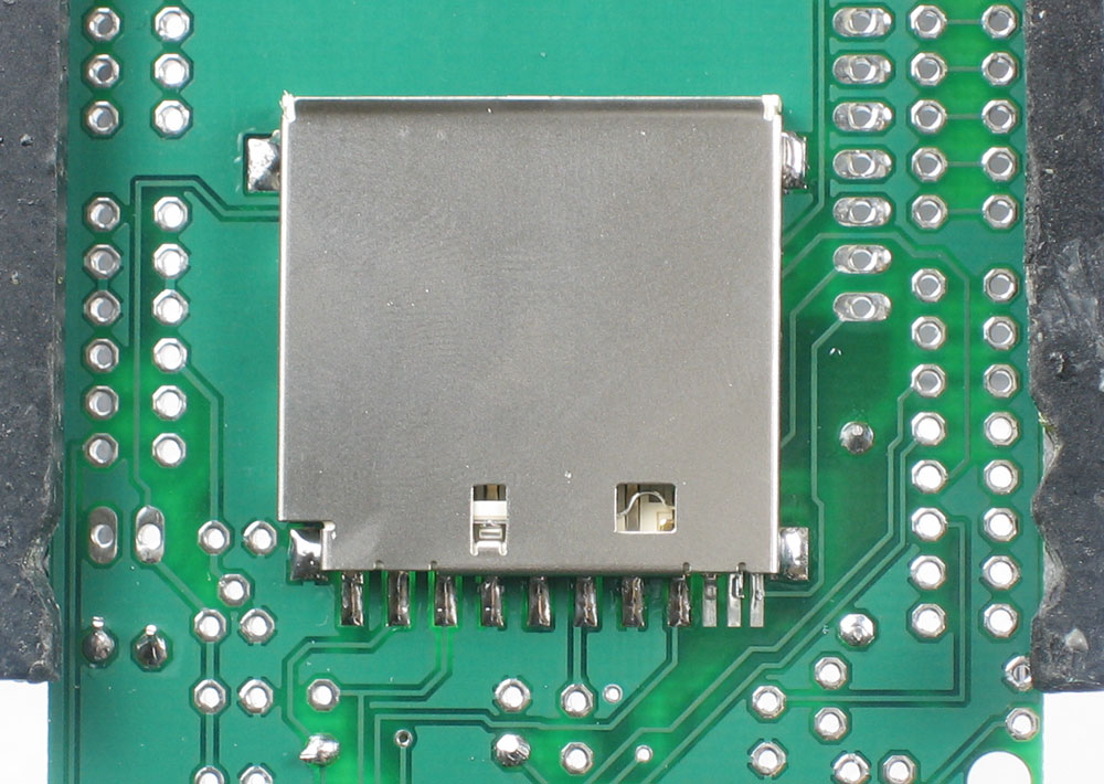
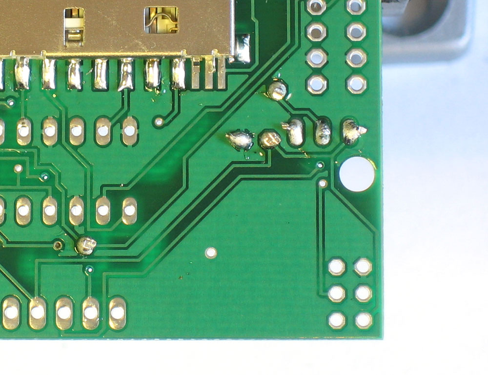
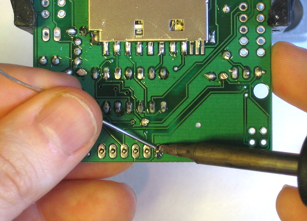
Next, solder the 7 large leftmost pins of the holder to the corresponding pads. Use a sparing amount of solder so that you wont end up bridging two pins by accident. If you aren't skilled at SMT soldering, you can simply skip the three smaller pins, they're not at all necessary |
|
Next we will install the three yellow ceramic capacitors C1 C2 and C3. Ceramic capacitors are not polar so they can be inserted either way and will work fine. Place, solder and clip the capacitors. |
|
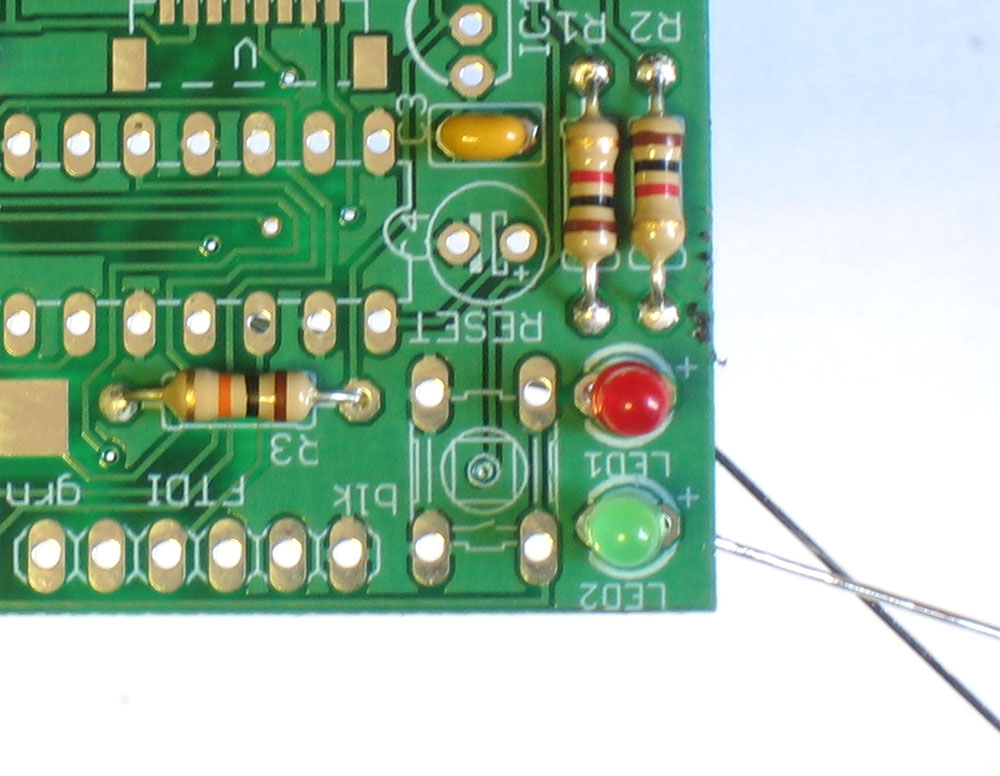
Next are the red and green indicator LEDs. LED stands for Light Emitting Diode, and like the zener diode, they must be place correctly or they wont work. To make sure the LEDs are installed properly, check that there is a lead that is longer than the other. This lead is the positive (+) lead. Make sure that this lead goes into the hole marked with a + on the PCB silkscreen, as shown. Another way to check is that many LEDs have a 'flat' side which marks the negative (-) side. Place both LEDs, it doesnt matter which color is LED1 and which is LED2 but the code examples will assume that LED2 is green. |
|
Solder and clip the two LEDs. |
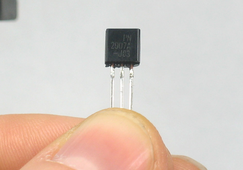 |
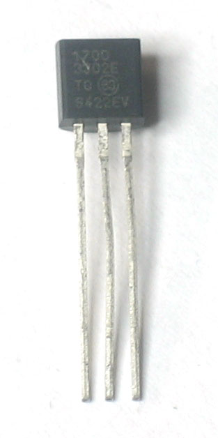
Next we will solder in the PNP transistor. The transistor is in a TO-92 package, with a semi-cylindrical plastic part and three legs. There is another TO-92 part which is the voltage regulator. These two parts look very very similar but are completely different so its important to look carefully and make sure that you are going to solder in the part that says PN2907A |
|
Insert the transistor into the location marked Q1. Because of the way the pads are layed out, the transistor wont sit flat against the PCB. Thats OK, it should stick up a little bit. Make sure the flat side of the transistor matches the outline on the silkscreen |
|
Solder and clip the transistor |
|
Now we'll place the 3.3V regulator IC1 which says 1700-3302E on it. Its shaped just like the transistor and goes in the PCB the same way, with the hemisphere matching the silkscreen. |
|
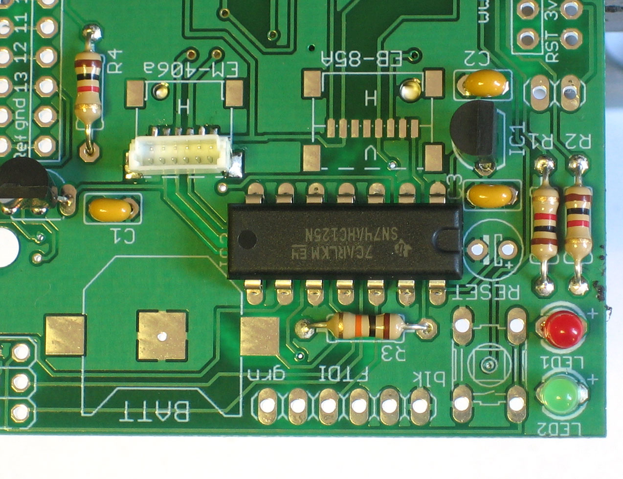
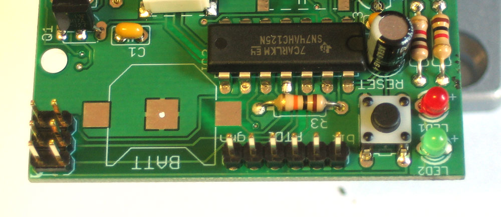
The next chip IC2 is the 74AHC125 which is the 3.3V buffer chip that converts the 5V signals from the Arduino to the 3.3V SD-card IC's must be placed a certain way, or they dont work. Make sure you get this right because if the part is in wrong its a real pain to fix! On one end of the chip is a round notch. In this photo its on the right. Make sure this notch matches the silkscreen underneath where there a similar round notch. Solder in all the pins of the chip |
|
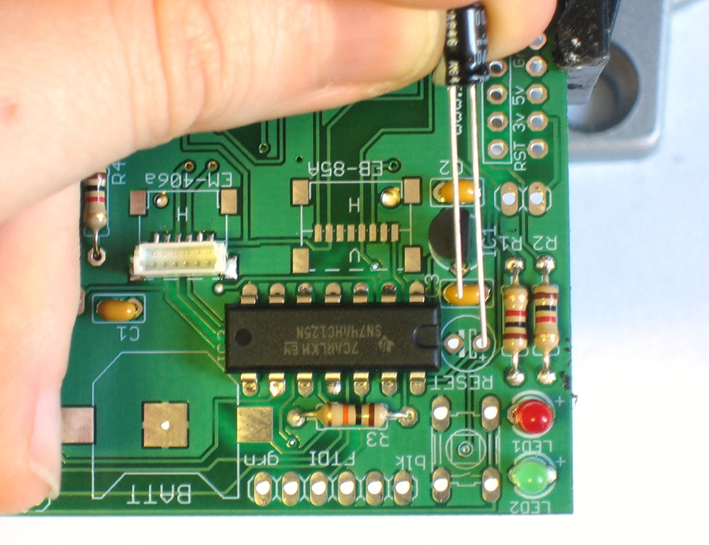
Next is the RESET button and electrolytic capacitor C4. Electrolytic capacitors are polarized and must be placed correctly. Like the LEDs, the longer lead of the capacitor is the positive (+) lead. Make sure this lead is placed in the hole marked with a +. The button is symmetric, snap it in place. Solder and clip |
|
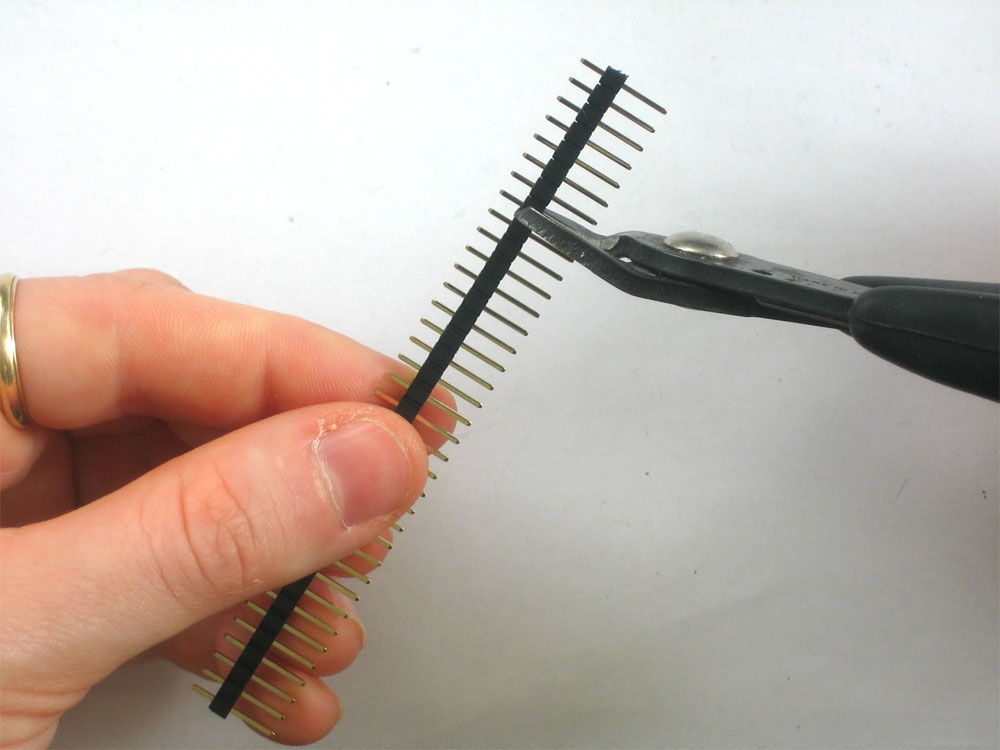
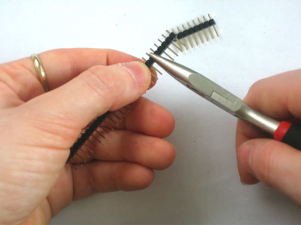
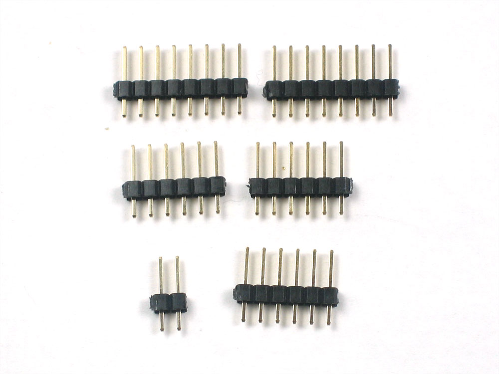
Next, break the 36-pin header strip into smaller sections so that the shield can be placed on the Arduino. You can use pliers or diagonal cutters. You will be able to perfectly snap the long strip into 2 8-pin strips, 3 6-pin strips and 1 2-pin jumper. |
 |
Place the 2x3 pin header into the location marked ICSP Make sure the long part of the header is sticking up. If you are planning to connect the shield to an FTDI USB-TTL cable (see the user manual for more information) then you should place one 6 pin strip in the header location marked FTDI.
|
|
Solder in the headers. You may want to use tape to keep them in place while you solder. |
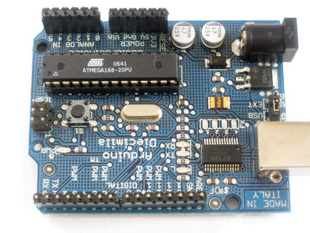 |
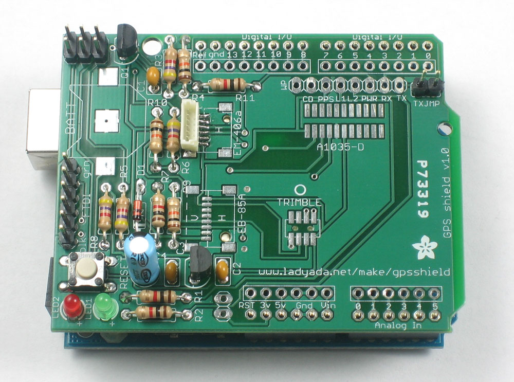
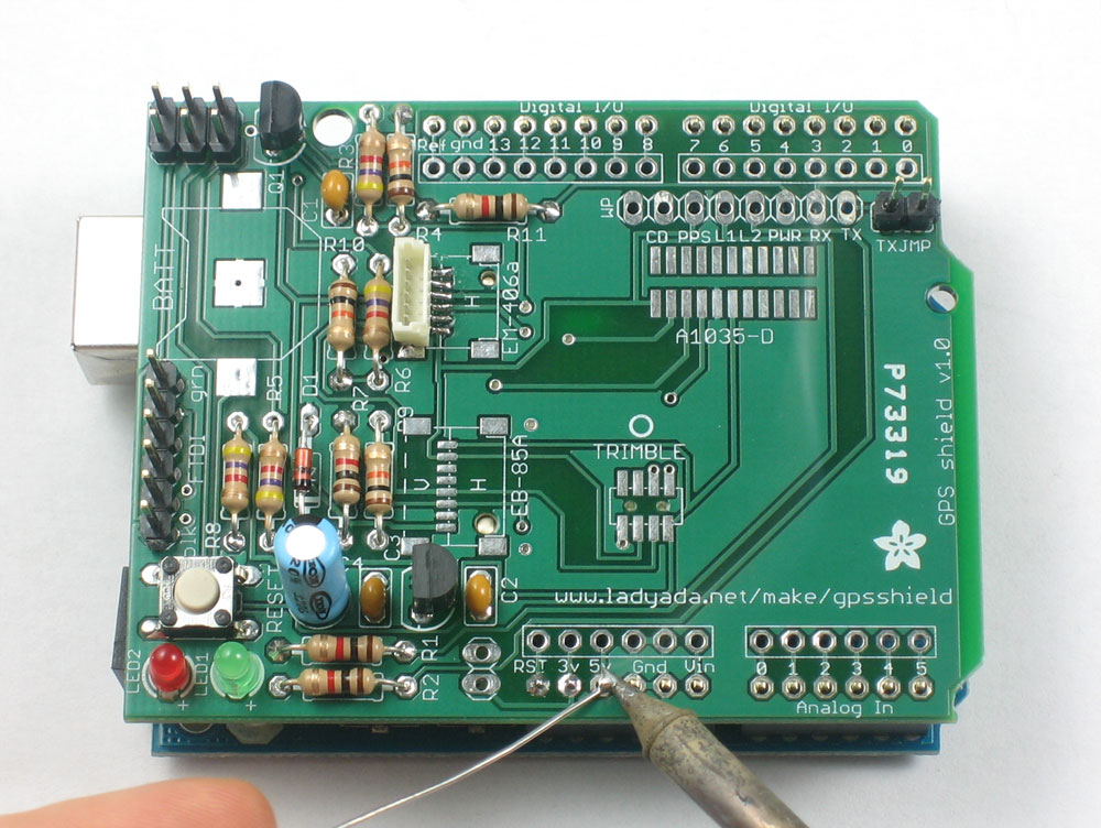
Place the 2 6-pin and 2 8-pin headers into your Arduino (make sure its not powered up when you do this, OK?) |
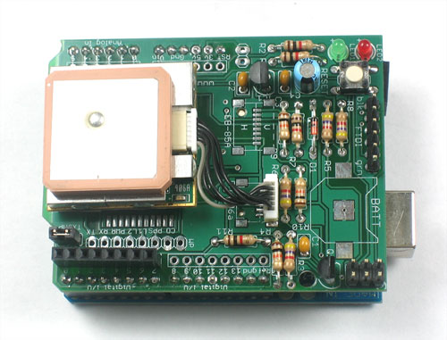
Slip the shield onto the Arduino as shown. The tips of the headers should all match up and poke through the shield. Solder all of the header pins. |
|
|
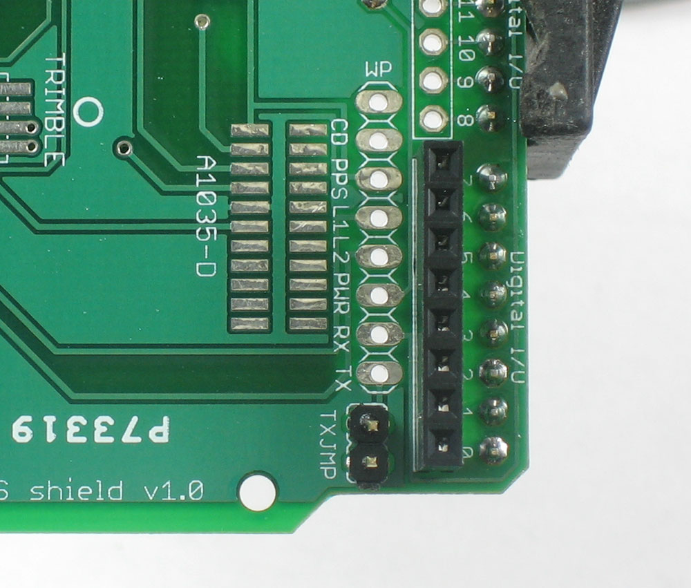
Place the 2-pin strip in the location marked TXJMP (its near the top). Make sure the long part of the header is sticking up. Finally, you will probably want to install the 8-pin female header into the digital breakout location as shown. This will let you do a bunch of hacking around while you're figuring out how you want to set up your GPS logger
Solder them in place |
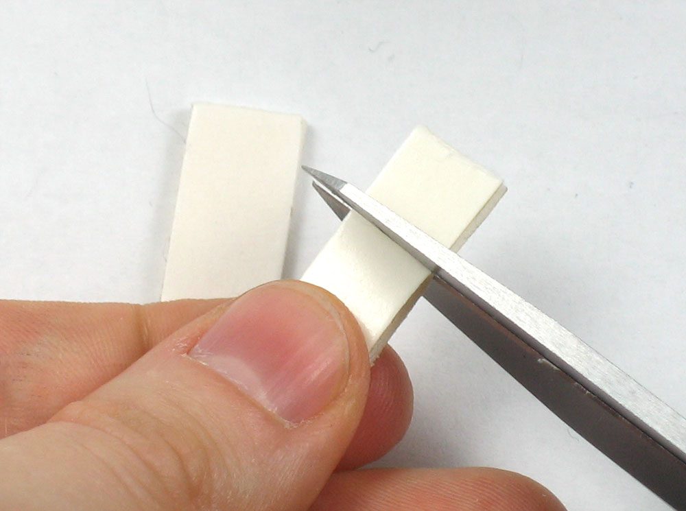 |
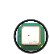
You can cut the foam sticky into quarters and peel off one side so that the GPS module will not sit directly on the shield (which could short a connection and damage the whole thing!) Dont remove the other side of the tape and permanently attach the module until you've done all the tests and configuration! (just in case) |
 |
Place the jumper into the TXJMP jumper location and go onto the user manual where you will learn how to wire up your shield for testing and use. |