
Once you have connected, its time to play around with the sensors and see how they are reacting, the main screen is the primary way for you to configure the device and sensors.
Once you are connected, you will see something like this:
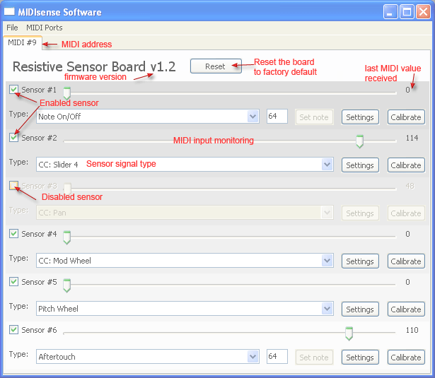
At the very top is a tab with the MIDI address of the MIDIsense board, as selected by the 4 dip switches.
Below that, there is a header with the type of board and firmware version. You can also click the Reset button if you have just updated the firmware or the device is somehow out of whack and you want to get it back to the factory default.
Below that is a section for each sensor - on the resistive board there are 6. Each sensor can individually be configured and monitored.
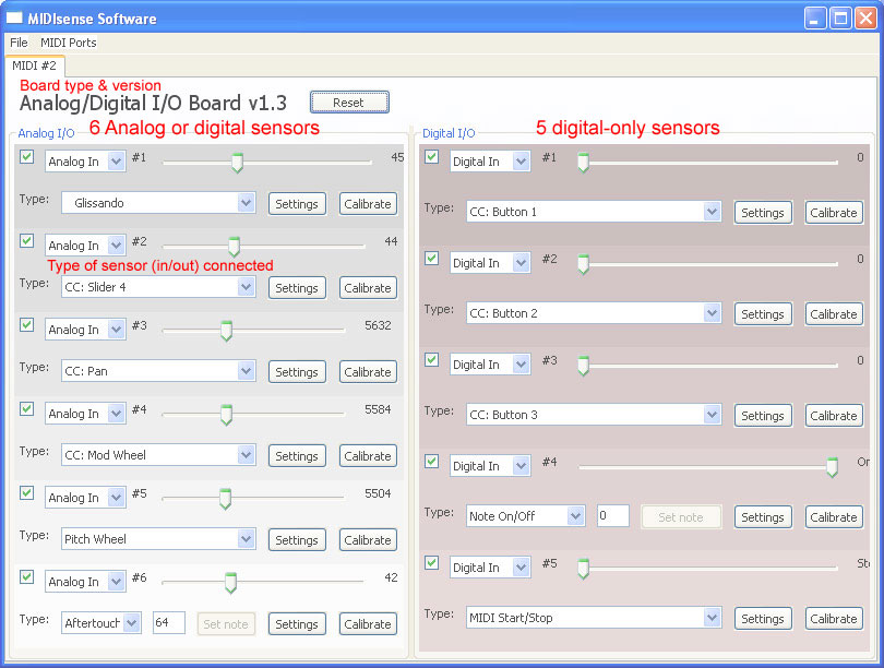
The Analog/Digital Input&Output board looks a little different. For one, has 6 analog inputs and 5 digital I/O ports, they are on two halves of the program screen:
Second you can set the type of sensor that is connected, using a dropdown menu
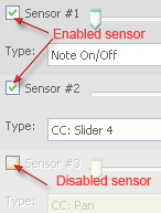
The first configuration for each sensor is whether it is enabled or disabled. That is the checkbox on the very left, next to the name. When it is checked, the sensor is enabled and will send data. When it is unchecked, there is no data sent for that sensor.
If a sensor is not connected, the port is 'floating' which means it can pick up electrostatic and RF which may send random signals. Therefore, it is suggested that if the sensor port is not being used to disable that sensor: it will clear up the MIDI connection and avoid confusion. You will get faster sensor responses and can send more data when you deselect unused sensors.
To make it easy to debug, there is a slider that acts as an input monitor. The software watches for incoming MIDI and displays it by sweeping the bar back and forth.
Click on the play symbol below to see the video of the slider in action. As this video was taken, I was waving my hand over the light sensor
To the right of the bar is a number which gives you the exact MIDI value most recently received.
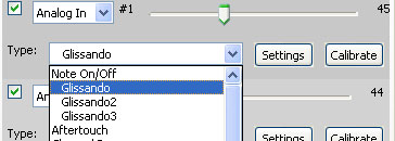
The pulldown menu below the monitor slider allows you to change the type of MIDI message sent.
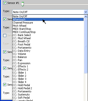
Messages types that start with "CC:" are Continuous Controllers, a subset of the MIDI standard that allows all sorts of different messages to be sent. Some are low precision (7 bits), some are high (14 bits), and will send a value between 0 and 127 (7 bit) or 0 and 16383 (14 bit) which corresponds to the sensor input.
Channel Pressure and Pitch Wheel are two continuous messages, but are not formally categorized as CC's in the MIDI specification.
Aftertouch is a continuous message, but has a particular note that it is associated with
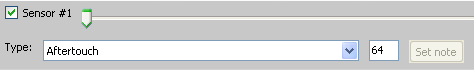
the note can be between 0 and 127, and is standardized in the MIDI specification. To set the note, type it into the box and click Set Note. The variable value is the pressure associated with Aftertouch.
Note On/Off is not a continuous message type: it sends only Note On and Note Off messages, with the velocity fixed at 64. To set the threshholds for on and off, use the calibration window (described in the Calibration section). You can change the note just like with Aftertouch
- MIDI Start/Stop and Start/Continue are also not-continuous.
Firmware v1.3 adds support for Glissando, which allows sending Note On/Off of varying pitch depending on the sensor value
All the message types except for MIDI Start/Stop/Continue have an address associated with them (not to be confused with the address of the board, which is set with the switches.) In v1.1 of the firmware, the address was the same as the sensor number. In v1.2 you can set the address in the Settings dialog. If you have 2 sensors with the same type and address you may get strange results because the MIDIsense software can't tell which is which. You can always configure and calibrate the sensors though (because that is done over SysEx which has specific addressing)
For most MIDI types, the possible values ranges between 0 and 127 (7 bits). Some types (such as Pitch Bend, Volume, Bank Select, etc) have a finer granularity (called "fine adjustment") which adds another 7 bits to give a range of 0 to 16383 (14 bits). The MIDIsense board itself has only 10 bits of precision (0 to 1023) Therefore a 7 bit (127 max) signal loses some precision.
If you want to get the most precise signal, use a 14 bit signal. Since the MIDI message is more precise than the data, not all values will be used. For example the lowest value is 0, the next one is 16, then 32. Still, this is more precise than a 7 bit value.
Note that some devices ignore the fine adjustment messages because they cant reproduce it with enough precision.
You may want to research a bit more on MIDI if you are not sure which messages you're looking to generate!
If you have the ADio board, you can also set the type of sensor connected
The 6 analog sensors have 4 options.
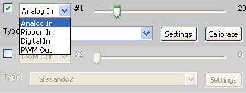
The four types are:
- Analog in
This means that an analog sensor (such as a potentiometer, Shart IR distance sensor, etc) is connected. The MIDIsense board will read the data from the sensor and transmit it out via MIDI - Ribbon in
This is a special-case sensor, called a ribbon controller. Ribbon controllers are special because when the person releases their finger from the ribbon controller, the analog input "floats", thus the MIDIsense board has to do some extra work to determine that a ribbon is connected and keep the last value. Otherwise, its just like an Analog input, it reads data in from the sensor and sends data out via MIDI. - Digital in
This means that the input is a simple switch, such as a pushbutton, reed switch, or toggle. - PWM Out (Pulse width modulation)
This is the form of output that the MIDIsense board handles. You can read more about PWM here at wikipedia. Basically, depending the MIDI message data, the board will modulate the duty-cycle of a 100Hz PWM signal. This is good for powering LEDs, panel meters, etc.
The 5 digital sensors have only 2 options, Digital In and PWM Out (which are just like above
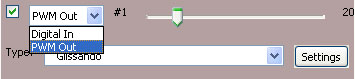
However, 2 of the digital sensors (#5 and #6) are special in that they have a third option
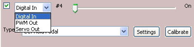
- Servo Out (Hobby servo-compatible pulse width modulation)
Small hobby servos use a form of PWM to communicate and set their speed or position. However, its a very fine-grained type of PWM which requires 40Hz frequency, and very low duty-cycle. By using the built-in 16-bit timers, the MIDIsense board can generate the very precise signal necessary. You can connect a servo up to either port or both (2 servos at once)